5 min read
This article explains how to transfer survey points and surfaces from Autodesk Civil 3D to tcpMDT using the standard LandXML format.
This procedure makes it possible to recover point coordinates and codes, as well as the geometry of triangulated surfaces or digital terrain models (DTMs), so that this data can be used in tcpMDT. It also shows how to verify the imported information and generate terrain profiles and contour lines.
Another article will explain the import of roads and roads from Civil 3D, one of the main interoperability improvements incorporated in tcpMDT 26.
Exploring the Project
1. Open in Civil 3D the drawing containing the data to be exported.
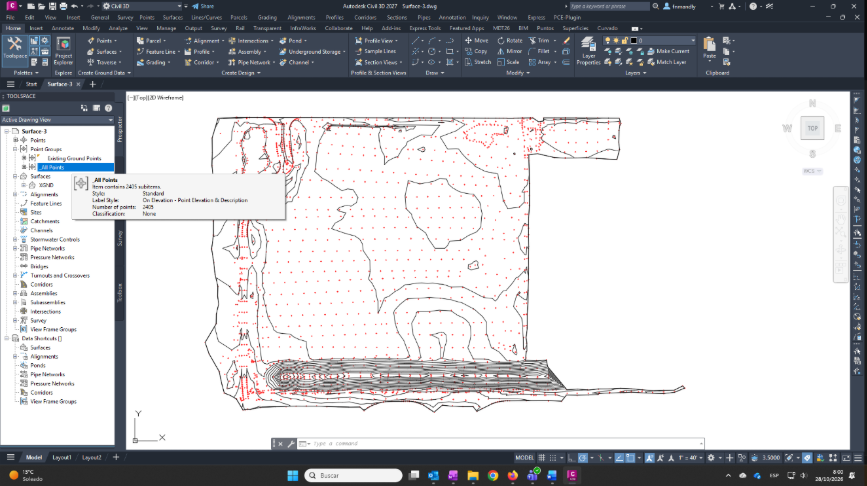
2. Next, examine the drawing. In Toolspace, on the Prospector tab, expand Point Groups, select All Points, and then click Properties.
3. Select the Summary tab and write down the number of points for comparison after conversion.
4. Select the Point List tab. Optionally, record the details of a point for reference.
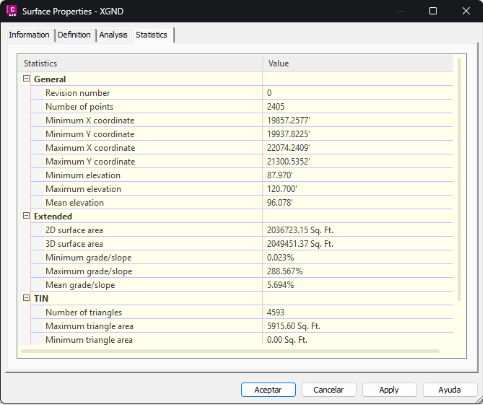
5. On the Prospector tab, expand Surfaces, select the surface to export, and click Surface Properties.
6. Select the Statistics tab and write down some values for later verification.
Exporting Points and Surfaces from Civil 3D
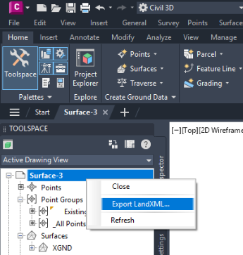
1. Back on the Prospector tab, select the drawing and click Export LandXML.
2. Deselect everything, then select only the point groups and surfaces to be exported.
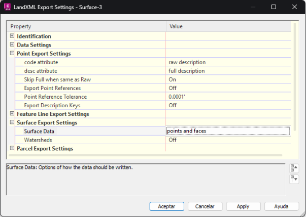
3. Next, click Edit Export Settings. Leave the point export settings at their default values. Under Surface Export Settings, check that Surface Data is set to points and faces.
4. Save the changes, click OK, and choose the name and location of the XML file to create.
Importing Points and Surfaces into tcpMDT
In tcpMDT 26, the import of surfaces using LandXML has been improved, also incorporating the breaklines, boundaries and islands defined in the original model. This allows more surface information to be preserved and facilitates the continuity of work between Civil 3D and tcpMDT.
The screenshots were taken in ZWCAD 2026, although the procedure is very similar in other compatible CAD versions.
1. In the CAD application, create a new drawing and set the same units as in the original drawing. In tcpMDT, also select the same units and coordinate reference system, where applicable.
2. Start tcpMDT and, optionally, create a project. Then run BIM > Import LandXML from the vertical menu or ribbon.
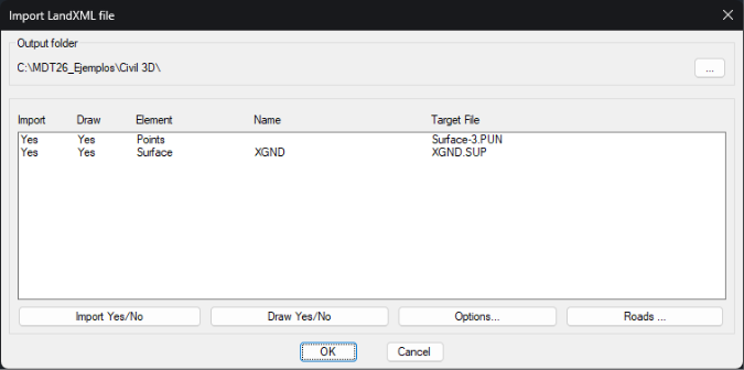
3. Select the previously exported file and click OK. In the dialog box, confirm that the points and the surface are listed. Keep the Import and Draw options enabled for each item, then click OK.
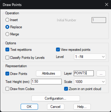
4. In the point import dialog box, choose an appropriate scale or text height. Leave the remaining options at their default settings and click OK.
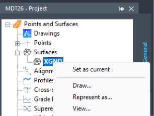
5. The breaklines and triangulation boundary defined in the original surface are preserved, as can be verified in the results. If there is more than one surface, select the desired surface in the project tree and choose Set as Current from the context menu.
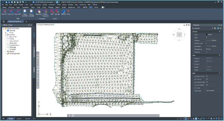
6. Hide the surface, zoom in, and check that the points have also been imported, preserving their point numbers and elevations, as well as the breaklines and boundary.
Verifying Imported Data
1. Now verify that the point data has been imported correctly. To do so, run Points > List Points. Check that the total number of points matches that of the original drawing.
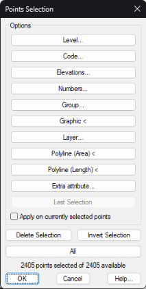
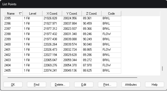
2. Select All and click OK. The imported points are listed with their numbers, X, Y and Z coordinates, and codes. Check that these values match the original file.
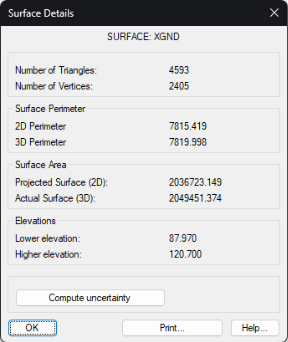
3. To verify the surface, run Surfaces > Information and compare the results with the original data, particularly the number of points, number of triangles, 2D area and 3D area.
Working with the Surface in tcpMDT
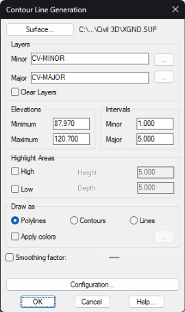
1. Next, generate contour lines from the surface. Run Contour Lines/Mapping > Create Contour Lines. In the dialog box, specify the intervals for major and minor contours, then click OK.
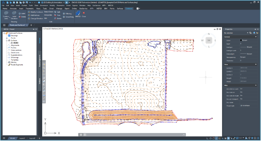
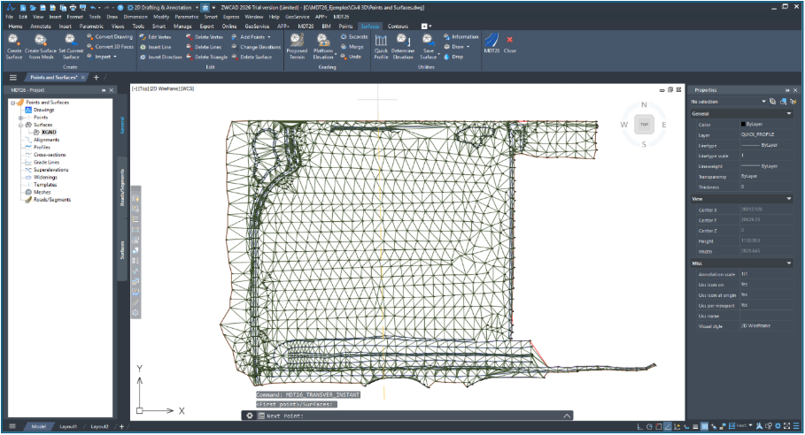
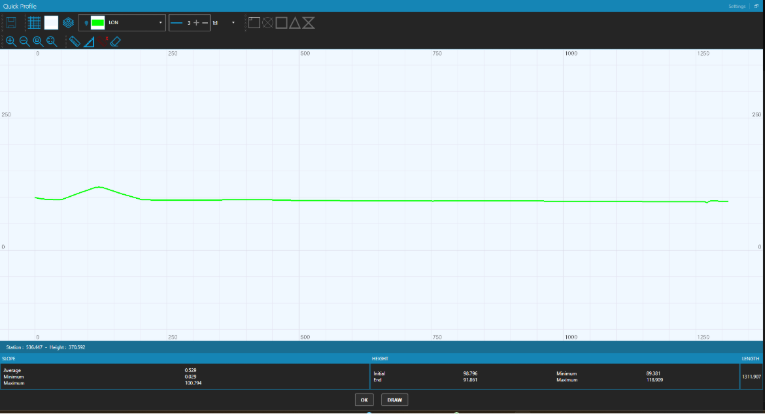
2. Show the surface layer and hide the contour lines. Run Quick Profile, selecting two points across the surface.
Frequently Asked Questions
Can I use Civil 3D data with tcpMDT on different CAD platforms?
Yes. Points and surfaces exported from Civil 3D using LandXML can be imported into tcpMDT, which is compatible with AutoCAD®, BricsCAD®, GstarCAD®, progeCAD® and ZWCAD®.
What topographic point information is retained when importing LandXML?
Point numbers, their X, Y, Z coordinates and their codes are preserved, allowing you to continue working with them in tcpMDT without having to enter them again.
Can Civil 3D surfaces be imported into tcpMDT?
Yes. tcpMDT allows you to import triangulated surfaces from Civil 3D using the LandXML format, preserving the original triangulation and respecting the geometry defined by the breaklines, boundaries and islands.
LandXML enables straightforward exchange of survey points and surfaces between Civil 3D and tcpMDT. Once the data has been imported and checked against the original project, you can continue working in tcpMDT, generating profiles, contour lines and other outputs without having to rebuild the source data.