The graphic control in Illustration 3 features a series of tools designed to facilitate the viewing of each of the elements selected.
We have a toolbar to control the Zoom, in addition to a control to provide each of the layers of the existing elements in the drawing with visibility.
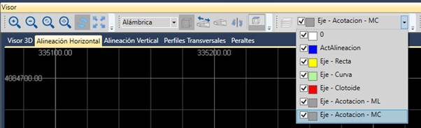
Illustration1:Zoom and layer control
Moreover, the graphic control is subdivided into several tabs to separate each of the representations:
· 3D viewer: Elevated view of the surface and alignment.
· Horizontal Alignment: Site alignments existing in the file.
· Vertical Alignment: Slope represented in elevation view.
· Cross-sections: Elevation view of the cross-sections, additionally, if there is a surface, the elevation view of the surface will be shown graphically in the station displayed.
· Cambers: Graphic view of the camber existing in the IFC file.