Once the trackers for one or more zones have been designed, this option allows you to create a theoretical surface for each zone in the project. The command has two modes of operation: selecting a zone in the drawing, or using the command line option Multiple or All.
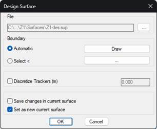
If you select a single zone, a window appears that allows you to select the name of the surface to be created.
By default, the program will automatically create an outline around the trackers in the area. In case this outline does not meet our expectations, we can use the Draw button to represent this outline in the drawing. Then, by canceling the command, and manually modifying the outline, you can recreate the design surface with the option to Select the modified boundary.
With the Discretize Trackers option, you can specify a discretization distance (every 5m, for example) so that vertices will be created along the longitudinal development of the tracker. If this option is not used, the surface will only include the start and end elevation of each tracker.
Optionally, you can also set the created surface as the current MDT surface. If a current surface already exists in MDT, you can save the changes to the surface that have yet to be saved by activating the corresponding option before switching to the new current surface.
If you select the Multiple option, a window will appear where you can select the zones you want to work on. You have to go to the list on the right of the zones on which you want to act.