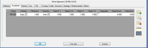
Roadbed thickness is defined as the existing thickness between the subgrade and the previously-defined vertical alignment. It has some internal and external slope values that will cut the platform defined for the template.
It is assigned by station and at the same time has a series of behavioral characteristics described below:
Criteria: Performance of the subgrade in the definition of roadbed. There are five performance types:
· Parallel: The subgrade is always parallel to the platform.
· Conditioned: The subgrade will take the maximum value from the value introduced in the box Pend / Cond.
· Parallel-Conditioned: The subgrade will be parallel except in other vector types such as lane vectors, to which a slope will be applied via the Pend/Cond. box.
· Slope: Subgrade has a slope value determined by the box Pend./ Cond.
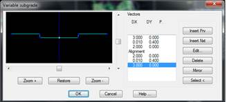
· Variable: This situation is for those cases in which the subgrade performs independently to the platform, without performing in any of the previously-defined ways. For this, once it is selected the following window is displayed to define subgrade platform vector.
On the left is a graphic representation and on the right is the vector definition with the corresponding buttons for editing. Among these buttons are the typical buttons to insert, edit, and delete, as well as the following buttons:
o Mirror: If the platform is the same on both sides of the horizontal alignment. Define only one of the sides and click this button.
o Select: If the platform is previously drawn in real dimensions in CAD, this option can be used to graphically select it and, in this way, it will read it and automatically build a list of vectors.
· Adapt layers: On selecting this option the subgrade will be defined in accordance with the roadbed layers defined for each of the vectors in the platform. In the event a vector has no associated roadbed layers, the roadbed thickness shall be that defined in the respective definition of the same.
Thickness: Absolute value of measurement to apply under the definitive vertical alignment of the platform. Is must be higher or the same as the sum of the layer thicknesses. Any change to this box will immediately modify the graphic image above in proportion to the other data.
Direction: Indicate whether to always apply, whether the section is cut or fill. The decision point to indicate whether the section is cut or fill is the horizontal alignment position.
Slope E.L.: Value of exterior left roadbed slope.
Slope E.R..: Value of exterior right roadbed slope
Slope I.L.: Value of interior left roadbed slope, this is only applicable in the case of templates with a median.
Slope I.R.: Value of interior right roadbed slope, similarly only applicable to templates with a median.
Interpolate: If this is activated it will interpolate the roadbed thickness between the station in question and the station assigned previously to intermediate stations.
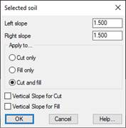
Selected soil: The thickness of the soil selected existing under the subgrade. If this value is edited the following window is displayed to configure the parameters of the soil selected.
· Left Slope: Left slope value of the soil selected.
· Right Slope: Right slope value of the soil selected.
· Apply to: Indicate whether to apply when the roadbed is cut, fill or in both circumstances.
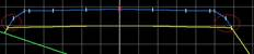
Below is an example of the soil selected in which the slope is different to the roadbed.
· Vertical cut slopes: If this box is activated, the slope of the selected soil in the cut situation will be built vertically until it reaches the slope of the roadbed.
· Vertical fill slopes: If this box is activated, the slope of the selected soil in the fill situation will be built vertically until it reaches the slope of the roadbed.
Functions of the different buttons on the roadbed definition panel:
 Insert a new roadbed assignment in a particular station. You can designate the station graphically in the drawing.
 Copies a roadbed to another station. Copies all the characteristics including the roadbed layers.
 Delete the roadbed selected.
 Removes all roadbed assignments.
 Edits the definition of the subgrade. This tab only works if the Variable criterion has been selected.
 Directly accesses the Selected Soil configuration explained above.
 If you press this button, you can define the roadbed layers associated with the selected roadbed. The definition of these roadbed layers only affects the lane, roadside and shoulder type vectors.
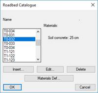
 When defining a new set of roadbed layers, if you have selected Spanish Regulations, the program will show the Roadbed Catalogue. In this way you can select the one that adapts to the road that you are going to define.
In the editing window you can make all the modifications that you need although the program will notify you in the event that regulations are not complied with.
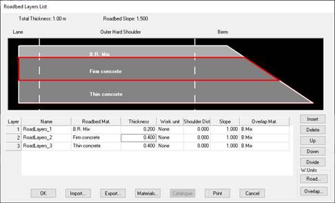
Once the regulations have been selected, the following window will appear where you will configure the different roadbed layers for your road.
The Roadbed layers are defined from the surface to the contact point with the subgrade. There are different ways of handling and managing the dialog box. It is possible to Import, Export and Print the detailed characteristics of each of them.
The top of the dialog box shows the total Roadbed Thickness and the value of the Exterior Slope.
Each layer has an associated customizable Name by the user, this name is the one that will be reflected in the export to the IFC format. See BIM chapter.
The list is entirely editable, so that the properties of each roadbed layer can be directly modified, and their order changed, any of them can be deleted and new ones created. The buttons: Up, Down, Delete and Insert are used for this.
Roadway Surface Material. Material assigned to the roadbed’s surface up to the external shoulder.
Thickness: Thickness of the roadbed layer. The sum of all the roadbed layer thicknesses can be no greater than total roadbed thickness.
Shoulder Dist.: Length of the overlap in the layer being defined. It is applied to the layer depending on the overlap selected.
Divide: If one of the materials assigned to one of the pavement layers is “Mixture B”, clicking on this button will automatically subdivide it into the following three materials, distributing the thickness equally between each of them:
· B.B. mixture.
· B.I. mixture.
· B.R. mixture.