A platform is defined as the set of vectors formed on both sides of the horizontal alignment, or from the median if there is one.
This set of vectors also configures the subgrade or surface supporting the roadbed. In other words, it will be used to calculate the excavation surface area. The ditch and/or the slopes will be situated at the ends of the platform should there be a cutting or fill surface.
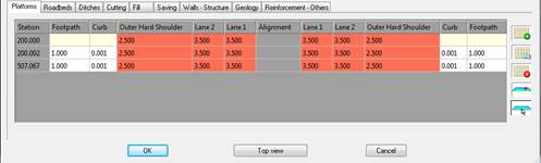
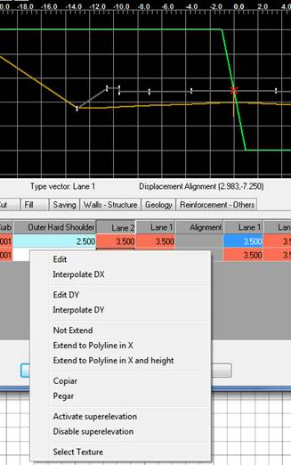
If superelevations are considered, they will be applied to the vectors selected. For this purpose, they can be marked by double clicking on the graphic representation or changing the corresponding vertex’s properties. They are clearly differentiated in the dialog box, because the vectors that can be superelevated are displayed in red, while the rest are displayed in white.
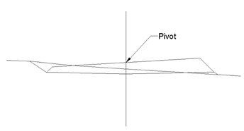
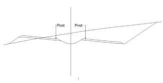
Additionally, defining the pivot element is essential, as it is at this vertex that grade line height will be applied and from where the superelevations are applied to both sides. The pivot vertex is represented in the image with a red arrow. For platforms with a median, two pivot points exist one for each roadway.
The data is introduced into a series of cells with the name of the vector in the top row, having previously been defined in the template. The first column is the station up to which the corresponding platform is applied.
The X displacement of the vector in question can be directly introduced in the cells. To apply a displacement in Y, double clicking on the desired cell a window appears for modifying this parameter as well as other characteristics.
If a cell is left blank, it is assumed that no vector exists for it, so that if in the previous or following definition one does exist, the vector will be automatically interpolated.
As previously mentioned, double clicking on any data cell displays a new window where the characteristics of the selected vector can be configured in more detail.
This window will be different depending on whether we edit a platform vector (Lane, Shoulder or Berm) or another type of auxiliary vector.
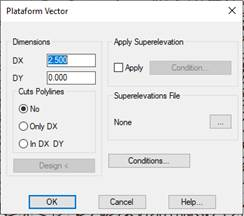
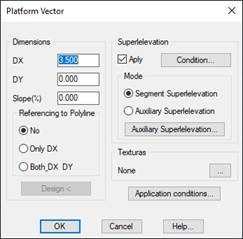
When editing a platform vector, the following window will appear:
DX: Horizontal vector displacement.
DY: Vertical vector displacement.
Slope: This option will allow us to enter a slope value for the vector and automatically calculate the DY value. Likewise, if we change the DY value, if it will automatically calculate the slope. The DX value will always remain unchanged.
Referring to Polyline: Option to designate a polyline on the ground to which the edited vector is stretched, if there is no intersection, it will take the default assigned value as the width of the vector.
Only DX: Only stretches in X.
In DX and DY: stretches in X and Y (Elevation).
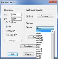
Texture: Optionally set the texture associated to each of the vectors. This option is used to give a more realistic appearance to the 3D representation commands available in the Maps option. If textures are not assigned, the program will automatically assign a texture when the above-mentioned commands are executed.
Apply superelevation: Indicate whether the vector can be superelevated. Click on the Condition button to customize the superelevation to apply.
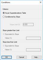
The superelevation will either be applied As per Superelevations Table or Conditioned by Slope. In the latter case, there are two criteria for the application of said slope: it can be either greater than or less than the limit set. There are two criteria for both alternatives:
Equivalent to Slope.
· A % value entered by the user (Value box).
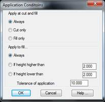
Application conditions: A series of conditions can also be applied to the vector according to which it will or will not be defined in the template.
Apply at cut and fill: This is to indicate whether the vector is applied according to whether it is cut only or fill only. Deciding on the vector application is the point of connection for the vector in the corresponding platform.
Also, if deciding that the vector is only applied to fill, there are three options:
1. Apply Always.
2. Apply if the height in regard to the previous vector is higher than a value entered.
3. Apply if the height in regard to the previous vector is lower than a value entered.
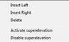
Selecting any of the names of the existing vectors and clicking the right mouse button displays a submenu with the following options:
Insert Left: Insert a new vector to the left of the selection, in this case a new window will appear with the vectors available to insert in this position.
Insert Right: The same as for the previous case, only this time the right vector is selected.
Delete: Eliminates the vector selected, completely eliminating the column selected.
Activate superelevation: Activates the superelevation in the vector selected, for all definitions at every station.
Disable superelevation: Similar to the previous only in this case it disables the superelevation in all the stations of the vector in question.
In the event that we select an auxiliary or non-platform vector, the following window will appear, in which the characteristics are similar to those of platform vectors, the difference being that a different superelevation can be applied to each vector.
Checking the “Apply” box under “Superelevation” will enable the “Application Mode” option.
Mode of Application:
1. Road / Segment Superelevation: The superelevation imported to the segment will be used as a reference for the vector being edited.
2. Auxiliary superelevation: Selecting this option will enable us to select a superelevation file. This superelevation file will be used as a reference to calculate the superelevation of the vector being edited.
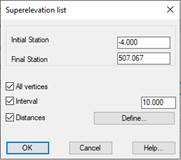
Auxiliary superelevation editing: If the “Auxiliary superelevation” option has been selected, clicking on this button will enable us to make a list of the superelevation in question. This is described in greater detail in the “List of Superelevations” section in the “Segments” module.
If on the contrary we select a group of cells belonging to the same type of vector and click on the right tab, the following sub-menu will appear:
Edit: Edits the vector selected. The same as double clicking on the box to be changed.
Interpolate DX: The option of interpolating the vector or vectors selected between two values specified by the user.
Edit DY: Enables us to assign the same DY to all the vectors selected.
Interpolate DY: In this case, we assign a DY to the first vector selected and another DY to the last vector selected; the DY arising from the interpolation is assigned to the intermediate vectors selected.
Not Extend: Deactivate the option for extending the vector specifying a pre-selected polyline.
Extend to Polyline in X: This option enables us to extend the vector selected to a polyline specified by the user; in this case it will only be extended in X.
Extend to Polyline in X and height: This is similar to the previous option only in this case the extension also applies to the height. The selected polyline should be in 3D in this case.
Copy: Copies the cell selected to the memory.
Paste: Enables us to copy the data from the cells selected from the copied cell using the previous command.
Activate Superelevation: Activates superelevation in the vectors selected.
Deactivate Superelevation: Deactivates superelevation in the vectors selected.
Select Texture: Enables us to assign a specific texture to the vectors selected.
For definitions of templates that have a median, the same properties of the median-type vector can be assigned to it. By double-clicking on the corresponding vector, the following window is displayed for setting up the configuration.
Median depth: Average depth of the median from the pivot point to both sides of the section.
Application point: Indicate here if the roadbed vectors connect at the crown or foot of the roadbed.
Additionally, there are four buttons for carrying out the following operations on the platform definition across the stations.
 This inserts a new platform assignment in a particular station. When the button is pressed it will request the station and once it is validated a line is inserted in the position where the vectors are assigned the values of the section with which the template was initially defined. Additionally, you can designate the station graphically in the drawing.
 With one of the platforms assigned to a specific selected station, this button makes a copy of the vectors at that station.
 Deletes the assignment of a particular station.
 Removes all assignments made.
 This button defines the platform pivot point, meaning the point from which the vertical alignment height will be applied and from which the left and right superelevations are applied. In order to do this first select the name of the vector on which to situate the pivot, then click the button.
The application point is shown with a red arrow in the vertex in question.
Platform pivot without median
Platform pivot with median
 With this button the program allows all the vertices of any polyline to be read, creating a new platform with its vectors.
First, the platform definition window disappears momentarily, to request the designation of a Polyline by placing the cursor on it. Then the Vertex corresponding to the Horizontal Alignment is selected. This is also done with the cursor; on the vertex we want considered as the horizontal alignment of the polygon.
The program will calculate the increases of the vectors drawn in their values (X and Y), with (0, 0) as a horizontal alignment of reference and restoring the dialog box for platform definition.
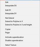
In addition to the aforementioned tabs for editing the platforms, we have a contextual menu with a series of options described below for each of the vectors of each of the platform assignments.
Edit: Edits the properties of the vector selected, similar to double clicking on any of the vectors.
Interpolate DX: We select a series of cells of the same type beforehand. On selecting this option, the program will request the initial DX and the final DX and interpolate the intermediate vectors.
Edit DY: Enables us to edit the displacement in Y of the vector or vectors selected.
Interpolate DY: The same function as the “Interpolate DX” option; but in this case for the displacement in Y.
Not Extend: Deactivates the option for extending the vector to s polyline when activated.
Extend to Polyline in X: This option enables us to extend the vector to a polyline specified below. It will only be extended in X.
Extend to Polyline in X and height: This is similar to the previous option only in this case the extension also applies to the height.
Activate Superelevation: Activates superelevation in the vectors selected.
Deactivate Superelevation: Deactivates superelevation in the vectors selected.
Select Texture: Enables us to assign a specific texture to the vectors selected.