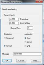
This numerical data element is used to label the coordinates of each vertex represented in the profile.
Evidently this element can only be labelled in the case of selecting the segment as it has the horizontal alignment information for calculating the coordinates.
Element height: Represents the immediately preceding numerical data’s distance to the element. This value can be expressed in two different ways:
· In number of characters.
· In Drawing Units.
When validating either of these, the other value will automatically recalculate.
Decimal Num.: Number of decimals of the values representing the partial distances between supports.
Orientation: Sets the text direction. There are two possibilities - Horizontal and Vertical.
Justification: Sets the text position in respect to the point of insertion. There are three possibilities: Start, Centre and End.
Message: Text that will appear as the element’s title on the numerical data drawing.
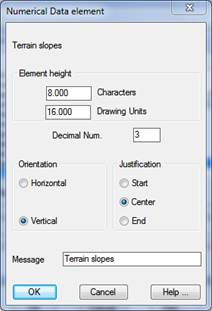
Terrain Slopes
This numerical data element will label the slope of each of the sections or vectors of the longitudinal profile.
Element height: Represents the distance to the immediately previous numerical data element. This value may be expressed in two different formats:
· Expressed in number of characters.
· Expressed in drawing units.
On validating either of these formats, the other value will be recalculated automatically.
Num. Decimals: Any numbers in the text in the column selected will be represented with the decimals indicated.
Orientation: Establishes the orientation of the texts. There are two possibilities, Horizontal or Vertical.
Justification: Establishes the position of the text in relation to the point of insertion. There are three possibilities: Start, Center and End.
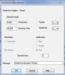
Grade Line Heights / Terrain
This numerical data element will display the height of the terrain and the height of the vertical alignment for each of the dimensioning’s together.
Element height: Represents the distance to the immediately previous numerical data element. This value may be expressed in two different formats:
· Expressed in number of characters.
· Expressed in drawing units.
On validating either of these formats, the other value will be recalculated automatically.
Num. Decimals: Any numbers in the text in the column selected will be represented with the decimals indicated.
Orientation: Establishes the orientation of the texts. There are two possibilities, Horizontal or Vertical.
Justification: Establishes the position of the text in relation to the point of insertion. There are three possibilities: Start, Center and End.
Terrain: We select the terrain for which the heights are to be labelled.
Vertical alignment: We select the vertical alignment for which the heights are to be labelled.
Message: Text which appears as the title of the element in the numerical data drawing.
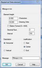
Mileage
Shows the distance to the origin in accordance with the interval configured in the element itself.
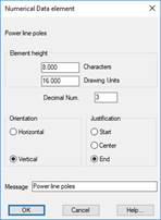
Power Line Elements
Poles
This numerical data element shows us the names or labels of the power line supports to be drawn.
These will only be drawn in the event the “Draw Power Lines” option has been activated and the file corresponding to the power lines has been selected.
Element height: Represents the distance to the immediately previous numerical data element. This value may be expressed in two different formats:
· Expressed in number of characters.
· Expressed in drawing units.
On validating either of these formats, the other value will be recalculated automatically.
Decimals: Any numbers in the text in the column selected will be represented with the decimals indicated.
Orientation: Establishes the orientation of the texts. There are two possibilities, Horizontal or Vertical.
Justification: Establishes the position of the text in relation to the point of insertion. There are three possibilities: Start, Center and End.
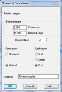
Rotation Angles
This numerical data element will label the rotation angle of each of the power line supports or poles.
These will only be drawn in the event the “Draw Power Lines” option has been activated and the file corresponding to the power lines has been selected.
Element height: Represents the distance to the immediately previous numerical data element. This value may be expressed in two different formats:
· Expressed in number of characters.
· Expressed in drawing units.
On validating either of these formats, the other value will be recalculated automatically.
Num. Decimals: Any numbers in the text in the column selected will be represented with the decimals indicated.
Orientation: Establishes the orientation of the texts. There are two possibilities, Horizontal or Vertical.
Justification: Establishes the position of the text in relation to the point of insertion. There are three possibilities: Start, Center and End.
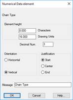
Chain Type
This numerical data element labels the chain type of each of the power line poles. There are two types of chain: Moorage and Suspension.
These will only be drawn in the event the Draw Power Lines option has been activated and the file corresponding to the power lines has been selected.
Element height: Represents the distance to the immediately previous numerical data element. This value may be expressed in two different formats:
· Expressed in number of characters.
· Expressed in drawing units.
On validating either of these formats, the other value will be recalculated automatically.
Num. Decimals: Any numbers in the text in the column selected will be represented with the decimals indicated.
Orientation: Establishes the orientation of the texts. There are two possibilities, Horizontal or Vertical.
Justification: Establishes the position of the text in relation to the point of insertion. There are three possibilities: Start, Center and End.
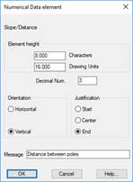
Distance between poles
This numerical data element labels the distance between each of the power line supports or poles.
These will only be drawn in the event the Draw Power Lines option has been activated and the file corresponding to the power lines has been selected.
Element height: Represents the distance to the immediately previous numerical data element. This value may be expressed in two different formats:
· Expressed in number of characters.
· Expressed in drawing units.
On validating either of these formats, the other value will be recalculated automatically.
Num. Decimals: Any numbers in the text in the column selected will be represented with the decimals indicated.
Orientation: Establishes the orientation of the texts. There are two possibilities, Horizontal or Vertical.
Justification: Establishes the position of the text in relation to the point of insertion. There are three possibilities: Start, Center and End.
Element height: Represents the distance to the immediately previous numerical data element. This value may be expressed in two different formats:
· Expressed in number of characters.
· Expressed in drawing units.
On validating either of these formats, the other value will be recalculated automatically.
Num. Decimals: Number of decimals to be represented in the values representing the red ground fill heights.
Interval: Interval representing the marks of the distance to the origin in the numerical data.
Station format: Possibility of labelling the station with the extended format (contains the symbol +).
Orientation: Establishes the orientation of the texts. There are two possibilities, Horizontal or Vertical.
Justification: Establishes the position of the text in relation to the point of insertion. There are three possibilities: Start, Center and End.