Exporting point clouds to Revit
First of all, to be able to export points to Revit in the correct manner, certain considerations need to be considered with regard to the coordinate system used in MDT and Revit. We normally work in DTM with UTM coordinate systems and, as such, the workspace within Revit needs to be configured to enable us to work with the same coordinates.
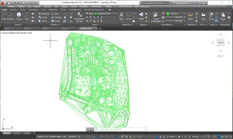
We have a drawing in the CAD in the coordinates of our example for this purpose, which we will then use to establish the coordinate system in Revit:
Based on a topographic survey and in accordance with the needs of each user, we can filter the points using the MDT tool > Points > Utilities > Filter points, defining a minimum and maximum distance between points, in planes or 3D.
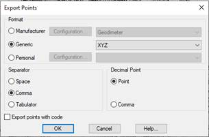
To export this point cloud to a TXT or CSV file in X, Y, Z format separated by commas, use the MDT > Points > Export command and add the TXT extension and disable the option to Export points with a code when saving the file.
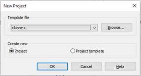
We create a new project in Revit, with no template:
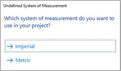
The system will ask us for the measurement system and we select metric:
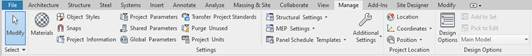
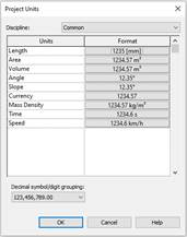
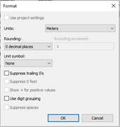
The first step is to configure the project in Revit in meters by selecting meters in the Manage > Settings > Project units tab under Length:
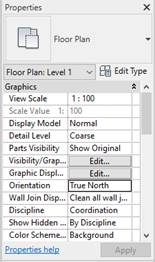
The next step is to change the Orientation to True North under current view properties:
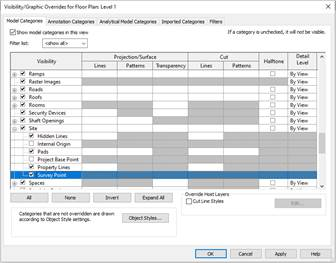
The next step is to visualize the Recognition Point entrusted with holding the project´s general coordinate system information, which should be located in the same place as all the models comprising our Revit project. It is displayed under the View > Graphics > Visibility / Graphics tab:
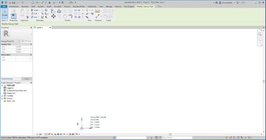
We then look for the Site property and activate Survey Point:
On starting a project, we can see that this point has no information on coordinates. Clicking on the symbol will show that all the values are set to 0 and that there is a paperclip symbol on the left. We double click on this icon until a red line runs through it to enable the recognition point coordinates to be changed when the real coordinates are transferred to the project.
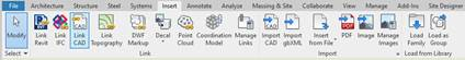
We are now going to link the DWG / DXF file containing the correct coordinates. To do so, use the Insert > Link > Link CAD tab:
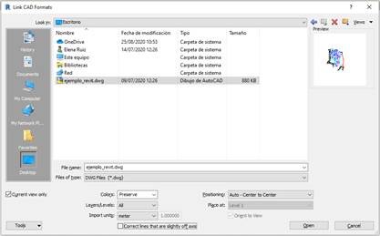
Under the CAD format link options, check the “Current view only” box; place meters under Import Units and “Auto – Center to center” under Positioning.
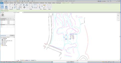
The drawing illustrates the centered DWG with the recognition point, which continues in 0.0 coordinates:
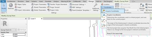
We then transfer the DWG coordinates to the Revit project, in the Manage > Project location> Coordinates>Acquire coordinates tab asks us for a linked project and we select it by clicking on the drawing.
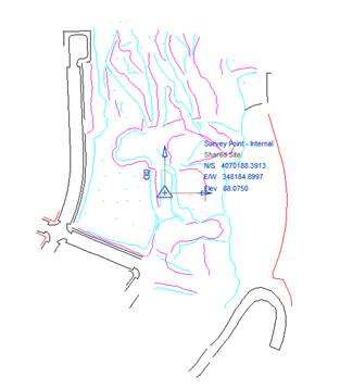
We can now see how the drawing and the recognition point are still central relative to each other, but that the recognition point coordinates have changed to the UTM coordinates in the drawing:
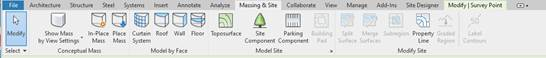
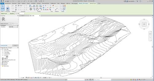
Once the project is located in the desired coordinates, we will be able to obtain a topographic surface from the import of a points file in TXT or CSV format. This is done using the Massing & Site tab > Model site > Toposurface tab:
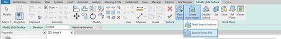
We use the tools downloaded from the Topographic Surface menu to select the “Create from import” command. Under the “Specify points files” option we then select our exported file from TcpMDT and click on the accept button  on the options ribbon, which will immediately show us the topographic surface calculated with their respective contour lines.
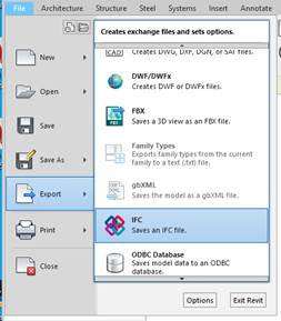
To finish, we export the surface obtained in Revit to IFC through the File > Export > IFC tab:
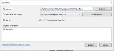
Select the “IFC2X3 Coordination View 2.0” format in the IFC export dialogue box to generate the corresponding IFC file:
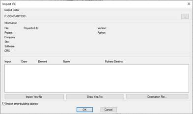
We the go back to MDT where the following dialogue box will appear in MDT8.5 > BIM > Import IFC, in which we need to activate the "Import other building objects" box by clicking on the accept button. We will then see how the corresponding surface is drawn (normally in white, change the color of the layer to be able to see it) and in the original DWG coordinates: