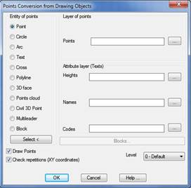
This tool allows on to easily convert drawing objects created in other programs that define points in space and that contain defined layers into TCP-MDT surveying points,
First, the Entity of points type in the drawing must be specified. If unsure, the Select button can be used to select the entity directly, keeping in mind that only the entities that appear in the window are recognized. For each type of entity, the program will create an MDT point in the following coordinates:
· Point: its own coordinates.
· Circle: Centre.
· Arc: Centre.
· Text: Point of insertion.
· Cross: Intersection of the two lines.
· Polyline: Initial vertex.
· Block: Point of insertion.
· 3D face: each one of the vertices.
· Points cloud: each of the points contained in the cloud. This option is only available for AutoCAD 2013 onwards.
As well as the entity type, the Layer of points that the program should analyze must be specified, except when converted into blocks.
As an option the program can search additional attributes of the point in text type entities. To do this the layers corresponding to each attribute must be specified.
Heights layer: The layer where the texts of the elevations are located. If they are not specified, each point is assigned its entity elevation, if it is in 3D.
Names Layer: Layer with the point names texts. If they are not specified, the points are automatically numbered.
Codes Layer: The layer where the assigned codes are located. If these are not specified, no code is assigned.
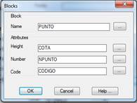
When the type of entity to be converted is a block, the Blocks button displays an additional window where the block attributes to be accounted for in the conversion are specified. If attributes are not specified, the program will do the same as with the other entities, and search for texts in the layers previously described.
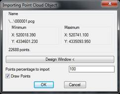
If converting points cloud type entities, a window appears providing information about the dimensions of the cloud and the number of points it contains. A smaller window may be selected or a percentage of the points to be imported. There is also the possibility of not drawing the converted points so as not to load excessively the drawing.
Draw Points: This box will be activated by default and will draw the points automatically. If it is deactivated, the points will not be drawn but will be stored in the memory.
Check Repetitions: Provides a report with the points which have not been converted due to the fact their coordinates have been repeated at another point.
Once the process has finalized, the program indicates the number of points created with the criteria above. The drawing’s original objects are kept unchanged.