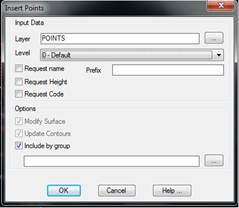
This command allows on to add points manually to a drawing. Firstly, a window is displayed where one can specify the level the points to be inserted belong and following options can be activated: Request Name, Request Height or Request Code, so that when the point’s coordinates are entered, the program will request the attributes enabled in the command line. Should there be a surface associated to the drawing, one can choose whether the point’s insertion will entail the insertion of a vertex on the surface (Modify Surface) or if the contour lines will be changes (Update Contours). Also, the option Include by group, allows for including the new points in a group of points.
Once the options above are set, one proceeds to insert the points. The program will repeatedly request coordinates and then insert the point in the drawing. If not specified otherwise, the points inserted will be assigned with the number of the last drawing point plus one as their name. If the coordinates entered are at a null height, the program will attempt to replace it for the current surface at these X and Y coordinates. The code assigned is “Inserted”.
Another possibility is to enter points by reference, which is useful when one knows the relative position of the new point regarding an existing point. If one answers R to the
Reference/<Point>:
question, the program requests the reference point’s number, which should be defined in the drawing. One then specifies the adjustment on plan either graphically or by means of AutoCAD’s usual syntax for two-dimensional points:
If x and y are entered, the points absolute coordinates are directly specified.
If @ dx, dy are entered, the program is informed about the coordinates relative to the reference point.
Lastly, distance and angle from the reference point are indicated with the @d<a format.
If a reference point is specified, the command carries on in this way until the command is finished.
Additionally, points can be inserted into the drawing in 2D or 3D, depending on whether the Draw in 3D check box is activated in the configuration of the Utilities Configuration Points command. It is usually advisable to draw them in 2D, as this subsequently facilitates editing lines connecting points and calculating surfaces.
