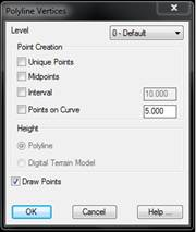
This command makes it possible to convert each of the vertices making up a polyline into surveying points, in addition to other options. The dialog box allows one to specify the Level of the new points to be created.
If the Unique Points check box is activated, the program inserts a point at each of the vertices (if it is not already inserted).
If the polyline is elevated (3D or 2D and elevation), the points take the height of the corresponding vertex. On the contrary, if the polyline is on the plane, the program will attempt to interpolate the vertices’ heights from points whose height is known. If this it is not possible, a height of zero will be assigned to all of them. Additionally, if the Digital Model is defined in the drawing, one can obtain the heights from it by marking the option carrying the same name.
If the Midpoints option is marked, a point will be inserted at each of the midpoints of the vectors making up the polylines. Independently, if the Interval option is selected, a point will be inserted every certain distance beginning from the polyline’s starting point.
If the Points on Curve box is marked, the polyline’s curved sections are also converted by the command. Points are inserted at the distance specified in the box to the right.
The Draw Points option controls whether the points to be generated with the command are to be drawn. It may sometimes be useful to deactivate it when a large number of points will be generated. Nevertheless, if one wishes to make a digital model from contour lines, it is more convenient to use the powerful model creation options offered in the Surfaces > Create Surface command.
Once the process has finalized, the program displays the number of points successfully created.