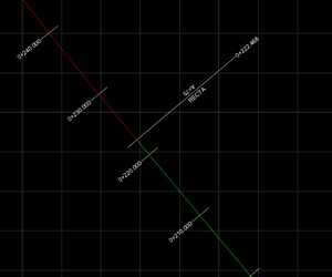
The alignment will be drawn on the CAD view as a set of polylines, one for each segment, along with its dimensions. Each segment type it’s represented with a different color, that can be adjusted on the layer configuration or, permanently, on the application’s settings.
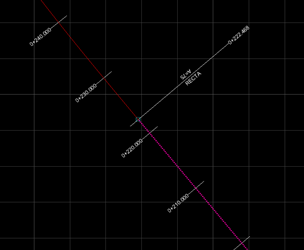
If an alignment’s segment is clicked, it will be highlighted on the CAD view and on the horizontal alignment’s panel. Once it’s selected, the segment will be displayed as a dotted line, wider, with the color inverted and with its vertices as hotspots.
From this moment, if we move the cursor over one of the vertices it will be highlighted, and the radial context menu will appear.