Volume by Simple Selection |
This command will be of enormous use in calculating the volume of a road with no complex sections, with no need to define everything in relation to standard sections.
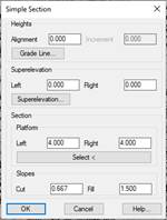
To do so, the program will first ask for the natural terrain cross-sections. The following window will then appear in which to specify the characteristics of the final terrain.
Heights: We select the height of the horizontal alignment of our road or take the height from the grade line selected. Moreover, on selecting the grade line file we can implement a positive or negative increase in the height of the station to be designed.
Superelevation: To specify the superelevations to be implemented on both sides of the horizontal alignment, which can also be executed using the superelevation file.
Section: To specify the characteristics of our section.
· Platform: There are two options for defining the platform:
o Specifying the breadth on each side of the platform.
o Designating a polyline to represent the platform; this polyline may feature as many vertices as necessary. One vertex should be in the horizontal alignment position.
· Slopes: Respective cutting or filling slopes.
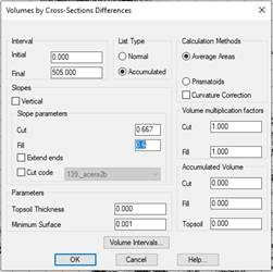
Once the values of the simulation of our road and its section have been entered, the program will ask for the type of list to be executed, in addition to a series of parameters required for the purposes of calculation. These parameters are listed in the section Volume by Cross-Section Difference section.
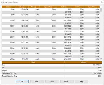
Once this window has been checked, a list will appear similar to the list of cubic measurements with all the information on the calculated surfaces and volumes, including the option to send the list to a printer or draw the profiles.
Volume by Plots 
This command enables us to calculate the volume of a group of plots from two surfaces.
On executing the command, MDT automatically reads all the plots featured in the drawing (to define plots, go to the Plots section in the reference manual), in the event there are no plots in the drawing the command will end, reason for which the plots to be analyzed need to be defined before executing this command.
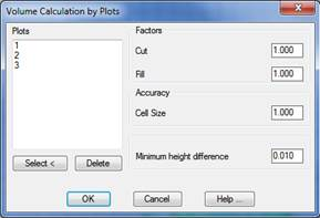
Once the plots featured in the drawing have been detected, the following window will appear, and which we will describe below:
Plots: Name of the plots detected in the drawing the volume of which is to be calculated. Plots may be Selected or Deleted with the aim of customizing the list.
Factors: These values are factors which multiply the calculated values of the respective surfaces. They may be used to consider the fluffing or compacting of earth in the calculation of the volume.
Cut: Multiplying factor of the cut surface.
Fill: Multiplying factor of the fill surface.
Size of the cell: To calculate the volume, MDT generates internally a mesh for each surface; this value refers to the size of the cell with which the mesh is to be created.
Minimum height difference. The minimum difference, in meters, at which the volume is calculated. In other words, in areas in which the difference in height between the two surfaces is less than this parameter, the volume of the surface will not be calculated, and this area will be regarded as void or zero.
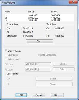
Clicking on this window will display all the information on the calculation of the volume of each of the plots.
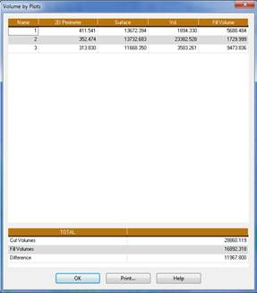
The Print button creates a list featuring the names of the plots and the information on the cubic measurement of each one:
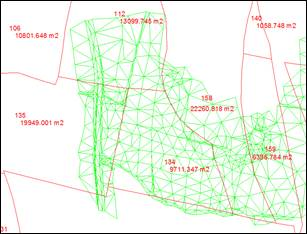
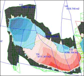
Activating the Draw Volumes box will provide a graphic representation of the results, consisting of a mesh located only in the area in which both mesh files are defined. Each cell will have a color indicating if the area is in cut, fill, or does not possess a volume within the limits defined in the settings. A range of colors may be assigned to both the cut and the fill; for this we have the option of selecting the corresponding color palette.
Moreover, if we activate the Differences in Heights box in each cut or fill cell, a text will appear with the difference in height between the meshes.