Under the CAD view we’ll see a panel with the current alignment’s information.
Add: It will show the Edit Vertical Alignment’s Node dialog so that we can set the new node’s Station and Height. At all times we’ll see, as a yellow dotted line, how the modifications will affect the definitive vertical alignment. If the insertion provokes an overlap, the application will warn us and won’t let us accept the dialog.
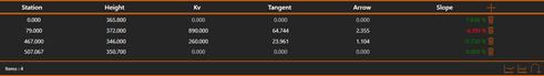
Node list:
For each alignment’s node, the following information is shown in the list. From left to right:
·Station: The node’s Station. It can be edited by double clicking it, it can only be confirmed if the new station doesn’t provoke an overlap.
·Height: The node’s Height. It can be edited by double clicking it, it can only be confirmed if the new height doesn’t provoke an overlap.
·Kv: Node’s vertical curve. It can be edited by double clicking it, it can only be confirmed if the new Kv doesn’t provoke an overlap.
·Tangent: Node’s tangent’s length. It can be edited by double clicking it, it can only be confirmed if the new tangent doesn’t provoke an overlap.
·Arrow: Node’s arrow’s length. It can be edited by double clicking it, it can only be confirmed if the new arrow doesn’t provoke an overlap.
·Slope: The node’s slope value. It’s the slope between that node and the next one. The slope direction is defined by the value’s sign. Positive slopes are displayed with a green text, negative ones with a red text.
· Remove: Removes the vertical alignment’s node.
Vertical alignment’s tools:
At the panel’s bottom right, we can find specific vertical alignment edition tools:
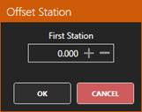
Offset Stations: Allow us to set a new initial station for the alignment, modifying the stations of each node.
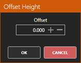
Offset heights: Allow us to set a height displacement that will be applied to each all the alignment’s nodes.