Slope Measurements Report |
As with the previous command, in these cases we can generate a list of the length of the slopes or the surface of the same. When selecting surfaces, the list may consist of developed or ground plan surfaces in the cut and fill slopes of the road of the segment selected.
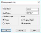
When this command is executed the following window is displayed:
Initial station: Station from which the list is made.
Final station: Station up to which the user wishes to make the list.
Type of calculation: We specify whether the measurement we wish to make is in elevation view, meaning a developed surface or a surface on ground plan.
Areas: Selecting this option enables us to see if the list to be generated features ground plan or raised surfaces, in other words, a developed surface or a ground plan surface.
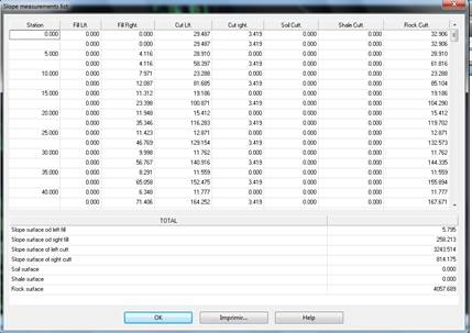
In the case of cutting, it also lists the three types of terrains that MDT analyses: Soil, Shale and Rock.
|
Works Units – Assignment to entities
|
This command will enable us to assign works units to significant entities in the drawing. More specifically, we can assign them to both lines and polylines and to specific blocks.
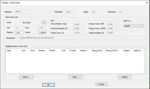
First of all, the program will ask us for the entity to which the Work Unit is to be assigned and once selected, the following window will appear in which we can select the Works Units. There is also the option of assigning a main unit and several secondary units.
This screenshot illustrates the works unit assigned to an entity, in this case a polyline.
The management of the assignment of works units is detailed in the Sections - Definition of Pavements section.
Works Units – Report
This command enables us to generate a report on the Work Units of the selected elements. The following items can be selected:
· Segments with pavement layers to which works units have been assigned.
· Earthworks to which works units have been assigned.
· Entities to which works units have been assigned.
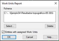
The following window will appear in which we add the segment or earthworks files. Furthermore, we can specify that the entities in the drawing with assigned works units are to be analyzed.
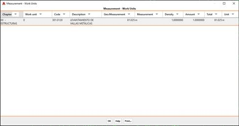
Finally, the following list will appear with the report:
Chapter: The chapter of the selected works unit.
Works Unit: The name of the assigned works unit.
Code: The code of the assigned works unit.
Description: A brief description of the assigned works unit.
Geometric measurement: The measurement of the element to which the works unit applies.
Unit of Measurement: The geometric unit of measurement.
Density: The density assigned to the works unit.
Amount: The amount assigned to the works unit.
Total: The sum of the product of the Geometric Measurement, Density and Amount factors.
Unit: The unit of the assigned works unit.
As with all the lists, it features the “Print” option with the possibility of sending the information to any of the available output options.
Works Units - Consumption and emissions report
This command, as with the previous command, will provide us with a report on the consumption and emissions of the selected elements.
First of all, we select the elements for which we wish to generate the report, whereupon the following window will appear in which we select the files with the segments, earthworks or entities we wish to include in the calculations and that have assigned pavement layers.
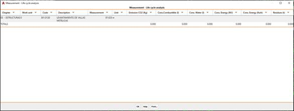
After checking the dialogue box, the following list will appear with the entire report.
The calculation of the different factors will be shown for each assigned works unit with assigned consumption and emissions.
The calculated measurement resulting from multiplying the geometric measurement by the density and the amount assigned to the works unit in question will be used as a reference.
The factors calculated are:
· CO2 emissions: Unit: kilogram.
· Fuel consumption: Unit: liter.
· Water consumption: Unit: liter.
· Energy consumption: Unit: mega joules.
· Energy consumption: Unit: Kilowatt / hour.
· Waste: Unit: tons.
Works Units - Material execution budget
This command enables us to calculate a budget for the execution of the selected elements. Each works unit will have a price assigned per unit, and the calculation will be made based on this price in accordance with the measurement of the element in question.
First of all, as in the two previous commands, the program will ask for the elements for which the budget is to be executed. In this case we will select tango segments such as earthworks or entities with assigned works units.
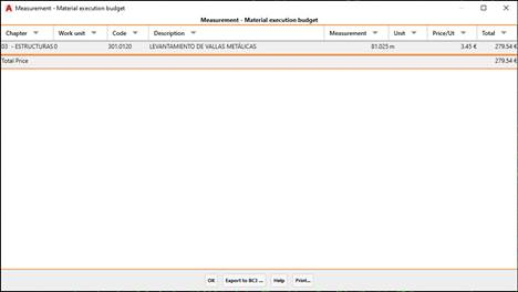
Once the dialogue box has been checked, the list with the estimate for both each works unit and the total will be displayed.
The calculated measurement resulting from multiplying the geometric measurement by the density and the allocation assigned to the works unit in question will be used as a reference.
· Chapter: The chapter of the selected works unit.
· Works Unit: The name of the assigned works unit.
· Code: The code of the assigned works unit.
· Description: A brief description of the assigned works unit.
· Measurement: The sum of the product of the Geometric Measurement, Density and Endowment factors.
· Unit: The unit of the assigned works unit.
· Unit Price: The price per unit.
· Total: The total price. The result of multiplying the unit price by the measurement.
This list includes the option of exporting the information to BC3, whereby clicking on the “Export to BC3” button will request the output file.
A BC3 file (also known as FIE-BDC format) is a standard file that enables the easy exchange of information between budget programs and databases, in this case, Civil Engineering.