This option is used to create a list of points analyzed in regard to the horizontal alignment or segment from an unlimited number of distances from the horizontal alignment in question.
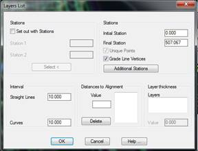
When the command is executed, the program first asks for the horizontal alignment or segment to be used in the setting out. It then displays the following dialog box:
The elevation of the point analyzed is always calculated from the height of the vertical alignment of the segment with the corresponding superelevation, according to the displacement selected.
Stations: The possibility of indicating the setting out stations exists, where Station 1 is the base station and Station 2 is the reference station. They can either be selected or their names entered in the respective boxes.
Initial station: Initial station from which the setting out will be performed.
Final station: Final station up to which the setting out will be performed.
Unique Points: If it is enabled, the horizontal alignment’s unique points will be added to the list.
Grade Line Vertices: If it is enabled, the grade line vertices in the segment will be added to the list.
Additional Stations: The possibility exists of indicating the command to calculate some additional stations.
Roadbed Thickness: All the layers that have been associated to the roadbed assigned will be displayed on this list, should there be a roadbed assigned. If no roadbed layers are assigned, the Grade Line and Subgrade will be displayed, offering one the possibility of setting out either of the two options.
In addition, the possibility of assigning a specific roadbed thickness exists. In order to do so, the relevant thickness should be entered in the Value box, so that the value will be subtracted from the setting out’s resulting height. Thickness should always be positive.
Interval: Value indicating the interval with which the setting out is to be performed. A different interval may be entered for Curves.
Distances to Alignment: Introduce the distances with their sign to analyses with regard to the horizontal alignment or segment selected.
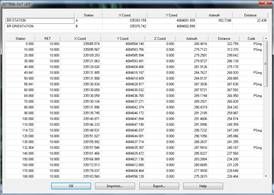
Once the dialog box has been validated, MDT performs a calculation with the aforementioned data and displays a list with the following information on each line: station and adjustment entered, in addition to the X, Y and Z coordinates. The Z coordinate will take values if a segment has been selected. The grade line height with the superelevation, if it exists, will be applied to it.
It is possible to export and print the data obtained from the final list, or to Draw Points. A description of each of the options follows: