This option allows us to project a set of points on a longitudinal profile obtained in the same work or model. In order to do so, it is necessary to have previously drawn the longitudinal profile on which one wishes to project the polyline.
When the command is executed, the program requests the horizontal alignment used to generate the longitudinal profile and then requests the profile. Once the two objects have been selected, the following dialog box is displayed.
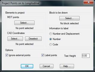
Elements to project:
MDT points: The points that one wishes to project on the longitudinal profile are selected. For further details on the point selection command, see the Points section.
CAD coordinates: Graphic selection of the coordinates we wish to label on the drawing; these need not coincide with the MDT points:
Block to be Drawn: The block that one wishes to represent on the longitudinal profile is selected. By default, the program loads all the blocks in the program’s BLOCKS folder.
Information to label: In addition to the block, there is the possibility of drawing the following information contiguously:
1.Number and Displacement: Number of the point and displacement to the horizontal alignment.
2.Number: Number of the point.
3.Code: Code of the planned point.
Ignore External Points: If any of the points projected on the profile are not within its environment, they will not be drawn if this box is marked.
Label Points: Activating /deactivating this box indicates whether to label the MDT point information.
Text height: Height of the texts for the label information.
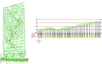
The command is run when the dialog box is validated. It inserts a block corresponding to the projection of each vertex of the 3D polyline on the profile. The following is an example of this: