This command generates a list with height comparisons of two previously-selected profiles.
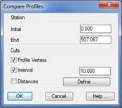
Initially it asks for the two longitudinal profiles to compare then the below window appears:
Stations: The stations the user wishes to compare.
Cuts: Indicate the cuts to be represented in the list:
Profile Vertices: displays all the stations of each longitudinal.
Interval: Indicates the representation interval.
Distances: Manual selection to represent specific stations, they may be manually introduced or designated in the drawing on the horizontal alignment.
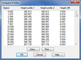
Once the window is validated, the following list will appear with the Station information and the heights of the two profiles.
Draw: This button automatically draws the profiles, so that we may simultaneously draw the two profiles with the correctly-configured numerical data.
|
Power Lines. Define Catenary
|
This command enables us to both define and draw a power line. Once the different parameters have been inserted both the electricity poles and the power lines themselves are drawn automatically.
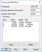
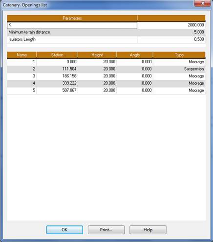
We first need to have drawn the longitudinal profile on which the power lines are to be drawn; we then execute this command and we will be asked for the drawn profile and the file in which the power line parameters are to be stored. The following window will then appear into which we insert the different parameters.
Parameter (K): The power lines parameter; the parabola of the same is defined in accordance with this data.
Minimum distance to the ground: Indicates the minimum distance allowed between the nearest points between the ground and the power lines vertically.
Insulator chain length: We define the length of the insulator chain. This parameter currently has no influence on the calculation or the drawing and will only appear in the corresponding list.
Verify: Clicking on this tab will cause the command to inform us if the power lines comply with the Minimum distance to the ground requirement.
Draw: The power lines will be drawn automatically whenever the Minimum distance to the ground requirement has been complied with.
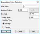
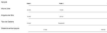
Pole data: This section enables us to define the different power line supports and posts. The Insert and Delete buttons will enable us to manage the definition of the same.
Pole Name: Identification of the support.
Insertion Station: Support insertion station.
Free height: Support height.
Rotation angle: Support rotation angle.
Insulator Type: Type of chain or coupling of the power line support, either of the Moorage or Hanging type.
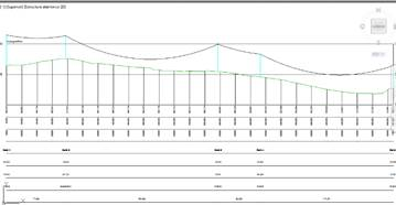
Once the power line file has been defined with the Draw Longitudinal Profile command from the longitudinal profile itself and the segment, we will be able to draw the power lines and the associated numerical data elements.
|
Power Lines. Delete Catenary
|
This command enables us to delete all the entities associated with the power lines. It will request the longitudinal profile on which the power lines have been drawn.
|
Power Lines. List Catenary
|
This command provides us with a detailed list of the power lines selected. The command will request the file containing the same.