Title: Once the profile is drawn, the title entered will appear on the top of the drawing.
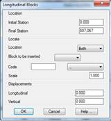
Blocks: This option allows one to select the blocks one wishes to draw on the longitudinal profile. At the same time, the Blocks numerical data element should be defined in the numerical data definition to be used
If the Configuration button is clicked, the following window is displayed where the insertion point of each of the blocks one wishes to insert along with the longitudinal profile should be specified.
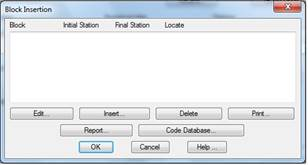
The following dialog box is displayed to insert or modify blocks for the longitudinal profile drawing.
Everything concerning the definition and management of blocks is explained in greater detail in the Blocks Definition section.
Blocks: This option only serves a purpose in the event a series of structures has been assigned to the template type. As such, if we activate this option a block will be drawn in the initial and final station of each structure. The block to be inserted may be selected.
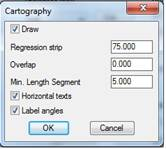
Cartography: This option allows one to view the sections of mapping adjacent to the alignment selected as numerical data elements.
In order to do so, only those layers corresponding to the objects one wishes to project should be active when the profile is drawn.
Concerning the objects supported, it is advisable to previously convert splines (should they exist) into polylines to ensure they are correctly represented.
It has the following configuration parameters:
· Draw: If this box is activated, the mapping will be represented in the lower part of the profile.
· Regression Strip: Strip to the left and to the right of the area to be drawn, in meters.
· Label Angles: When this option is activated, the program indicates on the numerical data element the existing angle between each of the alignment sections selected.
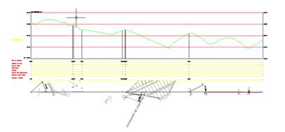
If map drawing is selected, the program requests the alignment one wishes to project when the main screen for drawing longitudinal profiles is validated.
An example of the outcome of applying this drawing option is shown below.
Structures: Activating this option will provide us with the possibility of drawing a block in the stations featuring an initial or final structure. Consult the template type section for information on the definition of structures.
Draw Catenary: Activating this box will draw the power cables associated with the longitudinal profile. The numerical data on the “electricity lines” will be configured by default. On validating the dialog box, the command will ask the user for the file containing the information on the power lines.
Profile length: This control will only be activated if the drawing is made on hard copy, in which case MDT will calculate the maximum length that can be drawn on each sheet depending on its format. The possibility exists of modifying this distance to adjust or give more margin to the representation.