In MDT, piping networks are stored in the drawing, and each of the entities created for the management of this module will have their own implicit properties.
We will distinguish between two types of elements:
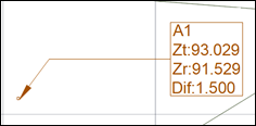
Nodes: Represent the connection points between the different piping sections. Their properties are as follows:
· Identifier: Name associated with the node.
· X, Y coordinate: Coordinates to be placed in the node.
· Ground elevation. Elevation of the node terrain. If the diagram features a surface, the software suggests the elevation of the insertion point of the surface as the value.
· Grade line elevation: Defines the lower elevation of the node or well.
· Depth This value defines the depth of the node, whereby the following relationship will always exist: Terrain Elevation – Grade Line Elevation = Depth.
In the drawing it is represented with a block selected by the user and a label with its visible properties.
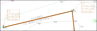
Pipes: Represents the existing pipes between the different nodes or wells. A piping section is defined between two previously inserted nodes or wells. They have the following properties:
· Identifier: The name associated with the piping section.
· Material: The piping material; the different types of materials can be customized in the settings section.
· Diameter The diameter of the piping section.
· Length: The length of the piping section.
· Slope: This value is obtained by calculating the existing slope between the initial and final node in the section.
· Direction: Represents the direction of the piping, or which way the liquid in the pipe moves. It is represented by an < o > symbol in the drawing.
The screenshot below illustrates the direction in the drawing, where the user can customize the items to be labeled.