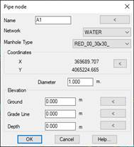
This command will enable us to graphically insert nodes at the designated point in the drawing. Once the coordinates have been specified, the following window will appear in which we place the characteristics of the node.
Name: The name of the node to be created. The text can be graphically placed in the CAD representing the name of the node.
Network: We select the Network to which the node being created belongs.
Manhole Type: When drawing the node, a block will be drawn at the insertion point, in this option we select the block to be drawn. These blocks are located in the block folder under the prefix “RED”. Users can add all the blocks they wish to use.
Coordinates: Node insertion point. Optionally, a new insertion point can be specified.
Diameter: Represents the diameter of the manhole.
Ground Elevation: The elevation of the top of the node. If the designated point is on a surface, the elevation of the ground at that point will be provided by default. In addition, the text representing the value of this dimension can be specified.
Grade Line Elevation: Represents the grade line elevation of the node. As in the previous case, the text can be placed graphically in the drawing.
Depth: The depth of the node. Changing this value automatically generates the change in the grade, whereby the difference between the ground elevation and the grade line is equal to the depth.
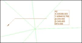
On checking the dialogue box, the node will be drawn in the selected coordinates, und we can select the items to be labeled under Settings.