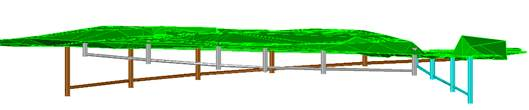
This tool enables us to obtain a 3D drawing of the piping sections and nodes. This drawing is executed using the “cylinder” feature in CAD, with the option of applying shade to the drawing in order to achieve a more attractive model.
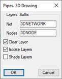
Layer Suffix: For each layer created in the drawing of the nodes and sections of piping, a new layer is created for the 3D model. This new layer will have the same name but will include the suffix specified in this section.
Clear Layers: Removes all the existing entities in the layers in which the 3D model is executed.
Isolate Layers: Only the layers in which the model is executed are defined as visible.
Shade Layers: Once the 3D model has been executed, the CAD shade effect is applied.