A Ditch is defined as the element added to the external edge of the platform. It is configured by adding vectors formed in a positive X direction to vectors given by coordinates associated to the origin or previous point. They move forward if they are positive (x) values. Ordinate increments (y) will be positive upwards and negative downwards.
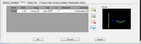
To the left the data for the ditch is introduced in the corresponding station and on the right is a preview of the ditch that is currently assigned.
Ditches: Number of the ditch assigned. All the available ditches are listed in the drop-down menu.
Apply: Indicate here whether the ditch is applied to cutting or fill.
Side: Side of the ditch’s application.
Cut: If this box is checked, and if the terrain cuts the ditch, it will be cut at this point.
Interpolate: If this box is checked the ditch will be interpolated between the current and the next one assigned.
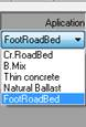
Application: The point of connection of the ditch, at the crown or foot of the roadbed. If we have defined the roadbed layers, this would give us the possibility of placing the ditch in a specific roadbed layer.
Control of Differences in Height: This parameter will enable us to monitor whether the ditch has been inserted in accordance with the difference in height in relation to the natural terrain at the point where the ditch is inserted.
The value will be set to “Always” by default, or in other words the insertion of the ditch will not depend on the difference in height between the vertical alignment and the terrain.
Additionally, there are buttons with the functions described below.
 This inserts a new ditch assignment. When the button is pressed the window below will appear for defining the ditch with which we wish to work.
 There are three areas:
Ditch: Buttons for moving forward and back over the course of the defined ditch library.
Ditches: Group of buttons for defining or deleting the existing ditches.
New: Creates a new ditch.
Delete: Deletes the current ditch.
Print: Prints the list of ditches with their vectors.
Select: This is used to graphically select a ditch which was previously drawn with an AutoCAD polyline.
Import: Imports ditches from a file.
Export: Exports ditches to a file.
Copy: Copies the current ditch to create a new ditch.
Vectors: The group of vectors comprising the ditch, with the corresponding buttons to insert, edit, or delete them.
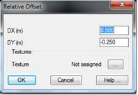
By selecting any of the editing buttons (Insert Prv., Insert Next, Edit ) the following window is displayed to specify the X and Y displacement that the ditch vector being edited will have.
It is important to highlight that the value of the X increment cannot be zero or negative. In other words, vectors always have to travel away from the horizontal alignment. Should a vertical jump need to be entered, a small value can be entered (such as 0.01 or 0.001), which will have practically no effect on the calculations.
In the Textures section the texture associated to each of the vectors can optionally be set. This option is used to give a more realistic appearance to the 3D representation commands available in the Maps option. If textures are not assigned, the program will automatically apply a texture when the above-mentioned commands are executed.
Once the dialog box has been validated, the list defining the current ditch will be updated.
When the ditch to be assigned is selected, a window appears for indicating the station up to which said ditch is to be assigned.
 Edit the ditch selected. The same window as in the “Insert” option will appear.
 Deletes the ditch assignment selected.
 Removes all ditch assignments made.
 Gives the option to graphically select a ditch that has been previously drawn with a polyline in real dimensions.
The last vertex at grade line height: the option of extending / removing the last vector of the ditch at the grade line height. The grade line should be selected beforehand using the “File” tab.
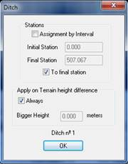
For the insertion or editing operation, as well as selecting the ditch, we must indicate the Station at which said ditch would be assigned and with this in mind, once the ditch has been selected the following window will appear.
We can carry out the assignment up to a specific Station or between a certain Station interval. With this in mind, we disable or enable the “Assignment by Interval" box. In both cases you have the option to designate stations graphically.
In addition, we will use this window to indicate whether the ditch is always to be inserted or whether this will depend on the difference in height between the point of the ditch and the natural terrain.
Coating thickness: Possibility to apply a thickness to the defined ditch. This thickness will be reflected both in the drawing of the vial and in the export to IFC (See BIM chapter).