Creating Pipes from Polyline
This option enables us to automatically define a pipe and its corresponding nodes using a polyline.
The nodes will be created automatically in each vertex of the designated polyline and, in additional, as defined in the Maximum distance between nodes parameter, the nodes we require will be added to ensure the maximum distance between nodes within a pipe is complied with.
Depending on whether the polyline selected is 2D or 3D, the command will behave differently with regard to the creation of the nodes and the piping itself.
First of all, it will ask us for the polyline to be converted and the following window will then appear with details of its characteristics.
Parameters: This data will depend on whether the polyline in question is 2D or 3D.
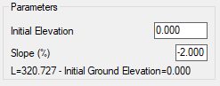
Selecting a 3D polyline:
We are only notified of the length of the polyline for informative purposes.
The nodes will be created automatically whereby the ground height of the node is the height of the surface at the node insertion point and the grade is the height of the polyline at the node insertion point.
Selecting a 2D polyline:
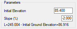
We are informed of the length of the polyline and the ground elevation at the initial polyline vertex.
This ground elevation will help us to define the grade of the section of piping. For example, in the screenshot, we will define a pipe with an initial grade line elevation of 85.400 with a negative slope of 2%. We now have an initial depth of 1.516 meters.
This data is then used to create the necessary nodes whereby the grade and depth of each of them will be calculated in accordance with the initial elevation of the polyline, the slope and the insertion point.
Nodes: The nodes to be created will have the following characteristics:
· Name Prefix: Nodes will be assigned a name iteratively starting from “1”. The ordinal will be prefixed with the value placed in this box.
· Network: The network of piping in which both the nodes and pipe sections are to be created.
· Well Width: The default width for the wells of all the nodes. Any node with a different width can be edited later.
· Maximum distance between nodes: The nodes will be created at each of the vertices on the polyline, and in addition nodes will be inserted at intermediate points on the polyline sections to ensure the distance between consecutive nodes is not greater than this value.
Pipe Properties: This section specifies the characteristics of the pipe to be created.
· Name: The name of the section of piping.
· Material: The type of material associated with the piping.
· Diameter: The diameter of the piping in millimeters.
· Grade Line Elevation: Point of application point of the grade line in the piping:
o Key: The top of the pipe
o Alignment: The middle of the pipe.
o Sheet of Water: The bottom of the pipe.
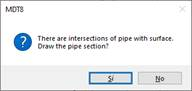
Once we have checked the dialogue box, if the software detects any intersection of the piping defined with the current surface (where applicable), the following window will appear, notifying us of such an incident and providing different options on how to proceed:
Label Intersections: The application will circle the points where the intersections have been detected.
Draw: We draw the pipe despite the intersections in the terrain.
Cancel: We cancel the drawing of the pipe.
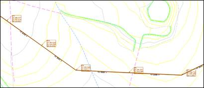
The pipe and their corresponding nodes will be created automatically.