With the CAD menu controls we can manage the CAD view:
Grid: Enable/Disable the grid
Background color: Sets the CAD view’s background color.
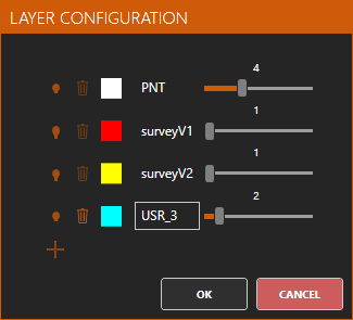
Layer configuration: Allow us to manage the CAD view’s layers. When we click the icon, the following dialog is shown:
Each layer has the following controls:
Visibility: Sets if the layer is visible or not.
Remove: Deletes the layer from the CAD. This is not always possible, there are special layers which can’t be removed and whose life cycle is managed by the application. In this case: the PNT layer where the lns files points are drawn and the layers for the longitudinal profiles in the lon files (one layer per file)
Layer’s name: Allow us to modify the layer’s name. There are special layers that can’t be renamed. In this case: the PNT layer where the lns files points are drawn and the layers for the longitudinal profiles in the lon files (one layer per file)
Line/Point width: Allow us to set the line/point width for the layer. Is bounded between one and ten.
Current Layer: Allow us to select the current layer. If we select a profile’s layer (it will have the same name as the file) that profile will become active. Also, layers can be shown or hidden by clicking the visibility icon
Global line width: Sets the line width for each layer simultaneously.
Vertical factor: Sets a vertical scale factor to apply to the heights in the CAD view. Allowed factors are: x1, x2, x3, x4, x5 and x10