This command will allow us to ascertain the correspondence of a point, entered using a cursor in the surroundings of a horizontal alignment or by entering the coordinates in x, y format.
Firstly, the program asks whether we are going to designate the points graphically, the MDT points to be found on the drawing or they are going to be read from a file and secondly the alignment is requested, and a segment may be selected. The user then enters a series of points in the manner stated. After each of these operations, in the commands area it will present us with the relationship characteristics with regard to the alignment with station and offset, as well as their coordinates, azimuth and radius. In the event that any point cannot be projected onto the alignment, this will produce the corresponding error message.
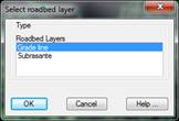
At Z-coordinate the elevation of the model at this point will be shown if we have selected an alignment.
If a segment has been selected, it will be shown in line with the standard section associated with the road and if there is no associated section, it will be calculated in line with the grade line elevation.
In addition, there is the possibility of entering a Layer Thickness and this will ensure that the grade line elevation to be shown is that calculated minus the layer thickness.
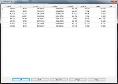
Once the points entering process is complete, we press <Enter> and the points calculation window will appear in the ground plan with the previous data listed.
On the final list there is the possibility of exporting and printing the data obtained. Below we have described each of the options: