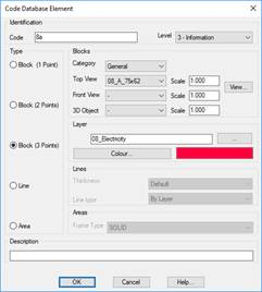
The parameters of the code selected can be modified by clicking the Edit button, whereupon the following dialog box is displayed:
For Block (1 Point)-type elements, three different blocks can be set. Each block is classified into categories (Signs, Miscellaneous, Vegetation, etc.), we first choose a category element before choosing an element of the block types. The Top View blocks are inserted with the Draw from Codes command. When longitudinal profiles and cross-sections are drawn, Front View blocks are used at the vertices having the relevant code. 3D Object blocks are used for the Route by Terrain and Route by Road commands. Each block has an associated scale factor that is multiplied by the specific scale used by the command.
Elements of the Block (2 Points) and Block (3 Points) type are similar to Block (1 Point) elements, but only the Plane category block is used. When a code is configured as a block with two points, it is only drawn if there are two points with this code. The coordinates of the first point coincide with the insertion point of the block and the distance and direction to the second point determine the scale and rotation of the block. The program assumes that the scale of the block is 1 m, and that it is drawn horizontally, from left to right. Hence, two points (0.0.0) and (0.1.0) insert the block as defined, the scale is 1.0 and the rotation 0.0.
The program works in the same manner for blocks with 3 points, only there are two scales. One horizontal, the distance between the first and second points, and another vertical scale that calculated as the distance between the third point and the straight line between the first and second points.
Each element in the database includes a field description where once can enter a more detailed description of what the code represents. This description can be included in points lists (see List Points command).