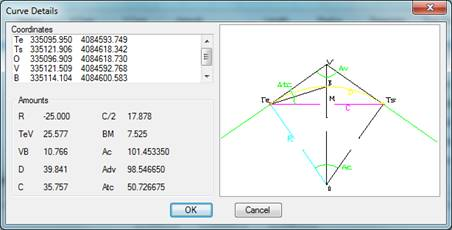
The curve type layout elements are defined by their center, initial and final angles and their radius. The latter will bear a positive sign if it moves forward in a clockwise direction or negative otherwise.
The coordinates sow in the Details dialogue of the command Edit Alignment
are:
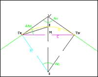
Te. Input tangent of the curve.
Ts. Output tangent of the curve.
O. Centre.
V. Vertex.
B. Bisector. Arc midpoint.
M. Chord midpoint.
On the other hand, the magnitudes indicated are as follows:
R. Radius.
T. Tangent
VB. Distance to the vertex: VB.
D. Development.
C. Curve length.
Sc. Semi-chord.
Fl. Arrow
Ac. Angle in the centre: TeOTs
Av. Angle at the vertex: TeVTs
Atc. Angle between tangent and chord: VTeTs
The circular curves are drawn as arc type entities or polylines with two vertices and curvature.
As with the straight lines, any kind of modification can be made to these elements using the CAD commands: copy, rotate, move, lengthen, shorten etc.