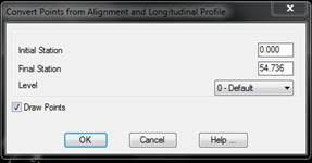
This command creates a point for each of the profile’s vertices from a graphically defined horizontal alignment or from either a horizontal alignment or segment file. The X and Y coordinates are calculated by interpolating the position on the horizontal alignment at each vertex’s station, while height is equivalent to the profile’s height. Each point’s code will be the code of each vertex should they be defined.
The dialog box allows one to perform this operation with a subset of profiles by entering the Initial station and the Final station, choosing the Level to which the points will belong and controlling whether they will be drawn with Draw Points check box.
Convert to Blocks with Attributes
MDT draws the points with its own type of entity by default, which means that when the drawing is opened on a computer without MDT, a warning appears notifying the user that there are entities that CAD does not know how to handle (proxy entities). In order to make drawings more compatible with users with no access to MDT or other programs, this command converts the points to block insertions with attributes. The program asks if the user wishes to delete the original points. If so, the information stored in the points as additional attributes (measurement data, uncertainties, geotechnical depths, etc.) may be lost, but the names, coordinates and codes of the points are kept. If they are not deleted, each point will appear in the drawing twice.