17.2. Surface Difference |
This command is identical to Mesh Difference command, except that it uses surface files as data input instead of mesh files. When the initial parameters are requested, a new additional element is displayed where one must enter Cell Size, which will be used to create the meshes used to calculate volumes.
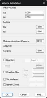
When executing the command, the program first displays a dialog where you can enter some Initial Volumes of cut and fill, which the program adds to the final result of the calculation. Factors can also be introduced that multiply the volumes obtained.
Once the two surface files to be used have been specified, the program calculates the volume, superimposing the meshes generated from the surfaces and informing the results obtained.
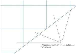
If the Create partial cells on the boundary option is activated in Settings > Volumes, in the event the cells on the calculation perimeter are only partially affected by the calculation of volume, only the affected region of the cell in question will be processed.
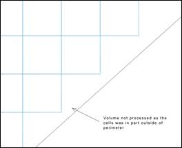
. If the option is not activated, the cell which is partially beyond the boundary will not be processed.
|
Create partial cells on the boundary
| |
 |
 |
|
ACTIVATED
|
DEACTIVATED
|
Minimum elevation difference. Minimum difference, in meters, to calculate the volume.
Boundary: We can select a polyline which delimits the surface we wish to analyze.
Topsoil: If topsoil thickness is introduced, the program internally lowers the elevation of the first mesh indicated meters, before proceeding with the calculation. This option will only be enabled in the case of selecting a boundary action, a boundary in which the displacement of elevation will be made for the calculation.
Elevation Filter: By enabling this box, we will be able to set the minimum elevation and maximum elevation values between which it is wished to make the calculation.
Volume Layers: This option will allow us to define different layers of terrain so that the cubing is shown separately for each of them.
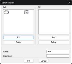
In this case, the clearing has been defined with two layers, one of 0.75 meters and another of 1.5 meters. In this way, the cubing will be broken down according to these strata of land.
Identify Zones: With this option we have the possibility of delimiting the different areas of clearing and embankment with a closed polyline. It is quite useful if we want to delimit the stockpiles.
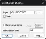
Layer: Layer on which the polyline is drawn.
Ignore small zones: If the area value is lower than the set and this option is enabled, those regions are not considered.
Identification prefix: Once the calculation is done, for each of the regions a table is labeled with the volume, this text is the prefix of the identifier of the table.
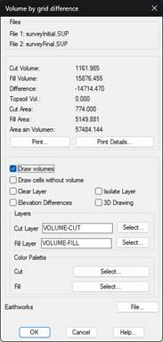
The Print button creates a list where the names of the surfaces files appear, and the results obtained. Furthermore, the Print Details button adds to the previous list a detailed breakdown of each of the mesh cells generated.
By enabling the box Draw Volumes, a graphic representation can be obtained of the results which consists of a mesh defined solely in the area where both mesh files are defined. Each cell will have a color indicating whether the area is being cut, filled or does not have a volume which falls within the tolerance defined in the configuration. There is the possibility of assigning in the drawing a range of colors both for the cut and fill; with this in mind, we have the option of selecting the corresponding color palette.
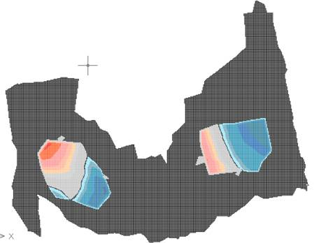
With the Draw cells without volume option, there is the possibility of drawing or not the cells corresponding to the areas where there is no calculated volume.
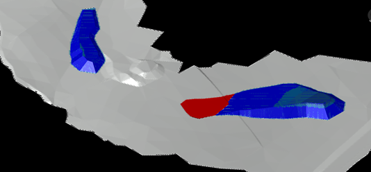
3D Drawing: If we activate this option, when the volume is drawn, a 3D view will be automatically applied and a shading will be applied over the cells.
In addition, if one activates the Height Differences check box, a text containing the height differences between both meshes will be drawn within each cut or fill cell.
Earthworks: Possibility of recording the information of the volume calculation in a file with an mt extension . This file will be useful if we later want to create a BIM model from the calculation made.
|
|