17.4. Stockpiles |
This tool will make it easier for us to quickly calculate the volume of the different land stockpiles that we may have on a surface.
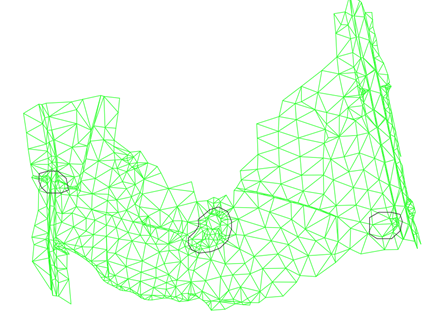
To do this, first of all, it is necessary to create a set of closed polylines that contains the land stockpiles that we want to calculate. These polylines, which we must draw previously, must pass through the base of the land stockpile.
When you run this option, the following window will be displayed in which you will manage the stockpiles to be calculated, as well as the management of the drawing of the volumes.
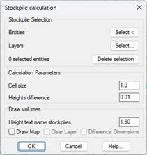
Stockpile Selection: There is the possibility of designating the polylines that represent the stockpiles either graphically or by selecting the layers in which they are located.
Once selected, the number of selected entities will be displayed, there is the possibility of deleting the previously made selection with the Delete Selection button.
Calculation Parameters
Cell size: The size of the cell for volume calculation.
Minimum elevation difference: When calculating the volume per cell, if the difference is less than this value, the calculated volume will be considered as null.
Draw volumes
Text height for names: Once the calculation has been made, the name of the stockpile is labeled on the drawing as well as the calculation made. This height refers to the text height.
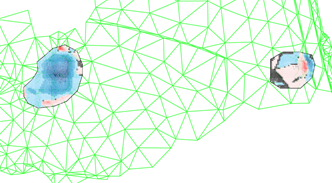
Draw Map: Draw a mesh in each stockpile with the cut and fill areas. Use the default associated palettes.
Clear Layer. Deletes all features on the layers on which the volume map is drawn
Elevation difference: Break in each cell the difference in elevation.
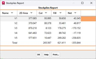
Finally, a list similar to the one that can be seen in the following image will be shown, with the calculation of volumes for each of the stockpiles.
|
Work Execution by Cross-Sections
|
This option will allow us to calculate the measurements of areas and volumes between different states of the terrain to be analyzed.
Specifically, you can enter up to four different situations of our project, when executing the command, the following window will appear:
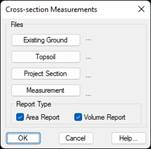
Existing Ground: Cross-sections of existing ground, before any earthworks. This file is required for the execution of the command.
Topsoil: Cross-sections of the terrain with the clearing applied, it is not necessary to select this file of transversals.
Project Section: Final status of our project. This file as well as the existing ground, is necessary for the calculation.
Measurement: Current measurement with respect to which the calculation would be made.
Report Type: It is possible to obtain two types of reports: areas and volumes.
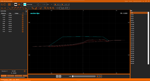
Once this window is validated, the transversal review window will appear so that the different overlapping profiles in each of the stations can be displayed.
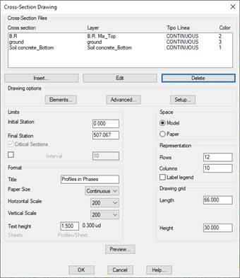
When you close the window, the following dialog will appear from which you can make the drawing of the cross-sections, similar to the Draw Multiple Cross-Sections tool.
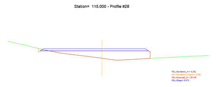
In the drawing we can check how the results of calculation for each of the areas are shown.
Finally, we will see the following report with the calculation of areas and volumes.
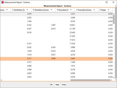
For each of the concepts we will see Inside or Excess. With Inside it refers to those that have been executed correctly and with "Excess" it refers to what has been executed too much according to the project section.
Likewise, the Pending will be shown both in dismantling and in embankment, what was executed correctly and what was executed outside the project section.
The prefixes "C" and "F" refer to the cut and fill respectively.
|
|