18.2. Route by Road |
This command is similar to the Route by Terrain, except that movement is now restricted to along the horizontal alignment definition.
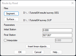
The program requests the following input data:
· Segment: Segment file containing the road’s geometric definition, including at least the ground plan alignment and elevation drawing, the cross-section profiles and the cross-section template used.
· Surface: Optional file used to generate the terrain upon which the road will be drawn.
· Initial station: Point at which the tour starts.
· Final station: Point at which the tour ends.
• Interpolate: re-generates the road at the specified interval to improve the accuracy of the road course.
In addition, the dialog has a button to insert linear objects that is explained below.
Insert linear objects
This option will allow us to insert 3D linear objects in the simulation of the road. The configuration of the selected objects as well as their location will be stored in a file. The file will be located in the same folder in which the segment is found, with the segment name and EL3 extension.
When pressing the button, the following window will appear from which the insertion of the objects will be managed.
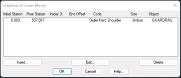
To manage the list, we have the Insert, Edit and Delete buttons. With the insertion or edition, the following window will appear from which the object to be inserted and its position with respect to the alignment of the segment will be configured.

Initial Station: Initial station from which the selected object will be inserted.
Final Station: Final station to which the selected object will be inserted.
Block to be inserted: 3D object to insert.
Side: Indicates the side on which the object will be inserted.
Locate: There is the possibility of inserting the 3D object at a vertex of our section or at a certain distance from the alignment.
· By Distances: In this case, we indicate the distance in the initial station and in the final station, interpolating in the intermediate stations.
· By Code: The object will be inserted in a vertex of our section, in the dropdown list we can select the vertex in which we are going to insert the 3D object. By default, the list will show the existing vertices in our section.
Click on OK to display the view screen.
See detailed description of viewer later.
|
|