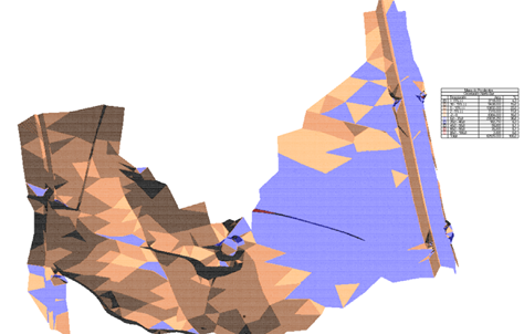
18.5. Draw Slope Map |
This command draws a map based on the current surface, assigning each triangle a different color based on its slope. By default, for each triangle the direction of maximum slope is used, but you can also select:
· North
· North
· East-West
· West
· Select: With the < button we designate the direction and direction of the slope.
Ignore Direction: If we activate this option, the direction of the slope is not considered, only the direction of the slope to make the map.
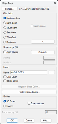
Slope range (%): Range of slopes that we want to analyze as a percentage. This option is useful if we are only interested in creating a map of a certain percentage of addresses.
Negative Slope Colors: We set the color palette and range for the set of negative slopes.
Positive Slope Colors: We establish the color palette and range for the set of positive slopes.
Entities
3D Faces: The slope map is drawn with CAD 3D Face entities.
·
Image: The slope map is recorded as an image. With the Transparency option, a transparency factor is set to the created image. The image created will be TIF formatted and will have the name of the surface file with the suffix "slope_direction".
Zone contours: If we activate this option, each of the groupings made according to the classification of slopes made in the color palettes will be delimited with closed polylines.
A layer will be created for each slope classification, the layer name will incorporate the configured slope range.
|
|