18.12. Assign Materials |
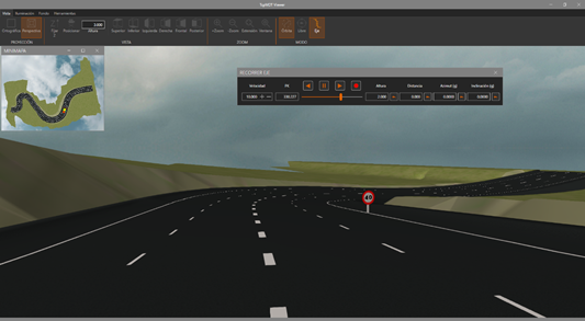
This command serves to manually assign a material to certain triangles on the current surface, with the aim of improving its presentation in the Terrain Route and Road Route commands. The Viewer is launched on closing the window.
Each triangle in the MDT surfaces file is associated to a triangle type indicator. When the program creates a surface, all the triangles or of Normal type. However, when the Earthworks or Obtain Modified Terrain commands are executed, they are assigned with another triangle type corresponding to the new triangles generated if the current surface is modified. Additionally, when one inserts a geo-referenced image using the Insert Image command, the program creates a new triangle type associated to the image and assigns it to all normal-type triangles on which the image is projected.
The following kinds of triangles are differentiated according to the command with which they are generated.
|
Type
|
MDT Command
|
|
Normal
|
Create Surface
|
|
EWSubgrade
|
Earthworks
|
|
EWCut
|
Earthworks
|
|
EWFill
|
Earthworks
|
|
Median
|
Modified Terrain
|
|
RoadBed
|
Modified Terrain
|
|
Ditch
|
Modified Terrain
|
|
Cut
|
Modified Terrain
|
|
Fill
|
Modified Terrain
|
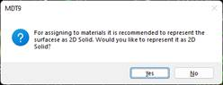
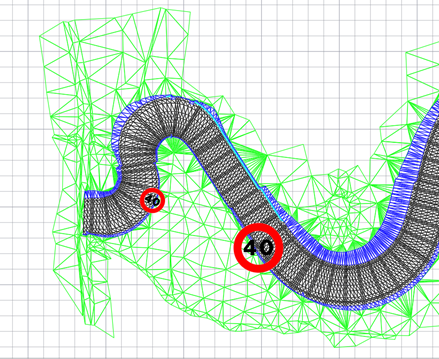
This command allows one to consult or modify the information about a surface’s triangle types. Firstly, a message appears enabling us to select the type of surface representation, 2D solids or polylines; we recommend working with 2D solids in order to take full advantage of the different colors of the materials.
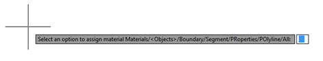
The image below illustrates a line of command and MDT25 - Maps > Materials/Objects on the options ribbon with the different options for the assignment of materials:
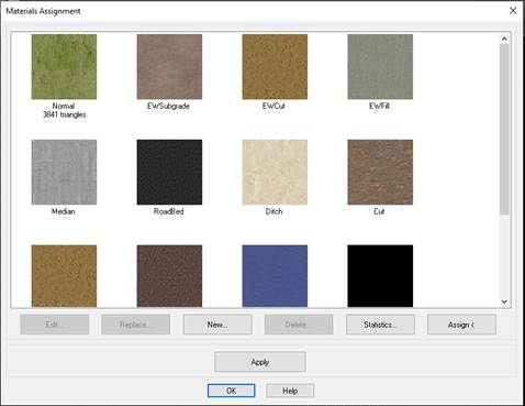
Materials: Shows a text box enabling the user to select different materials and conduct different operations.
Edit: enables us to change the color and / or texture of a type of triangle.
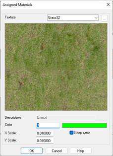
The Description of the material is for informational purposes. It describes the type of triangle in which the material is to be used
The Color of the material is used in case of not using the option to assign materials under the Draw Solids command. In this case the execution of the command is faster.
The Texture indicates the type of texture to be used in the material in the model.
Replace: enables us to change material for another.
New: enables us to create a new type of triangle for use with one of the assignment options.
Delete: removes the types of triangle which have not been predefined.
Statistics: covers the current surface and shows a list of the types of triangles assigned.
Select: Enables us to designate a triangle on the surface to use the material of the selected triangle.
Color/Texture: With this button there is the possibility to assign a textured material or a flat color.
Apply: Enables us to see the changes in the drawing when applying texture using any of the following options when the mode of model selected is SOLID 2D.
Objects: enables us to select the triangles to be modified by selecting entities of the 3DFACE, 2DSOLID or POLYLINE type.
Boundary: we need to select a closed polyline which delimits the triangles to be modified.
Segment: requests a segment file used to generate an internally modified terrain and copies the types of triangles (Median, Platform, etc.) to the current surface.
Properties: enables us to select one or more triangles and features a text with the name of the material in a dropdown list on which we can select another material and replace the triangles selected with the new one.
Polyline: we need to select a polyline and apply the material to all the triangles whose edges cut that line.
All: applies the material selected to all the triangles.
The Surfaces > Represent As command is used to change the way of representing the surface.
To see all textures supplied with the installation, consult the Textures section in the customization manual.
|
Assigning images as texture
|
Having a surface in the drawing and an image inserted enables us to select this image and assign it to the surface as a texture.
|
Insert 3D Objects
|
This command allows you to insert blocks into the drawing at the ground level that has the current surface, based on the designated points. There are two options: insert 3D objects individually, or along an axis.
To see all the 3D objects supplied with the installation, see the 3D Objects section in the customization manual.
Initially, the following window appears in which we designate the object to be inserted, depending on the selected object, it can have a block assigned to it in plan or in 3D.
3D objects will be displayed with the Route by Terrainand Route by Roadcommands.
This association between the object and the block is made in the Code Database command, within the Points section.
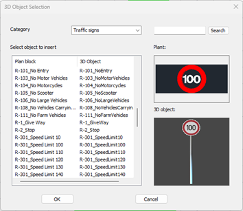
Category: By default, three types of categories are distinguished: Vegetation, Signs and Miscellaneous.
Once we select the object to insert, pressing the OK button will display the following window in which we will indicate the location of the selected object.
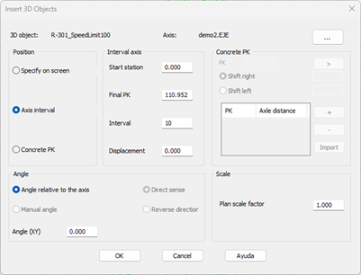
Alignment: If the object is to be inserted relative to the axis, the corresponding axis file must be selected.
Position
Specify on screen: After pressing the OK button, the points where we are going to insert the selected object are graphically designated on the screen. The corresponding block will be inserted automatically into the plan.
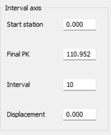
Alignment interval: We indicate at what interval the object is to be inserted with respect to the alignment. We set the Initial Station, Final Station, Representation Range, and Offset with respect to the alignment (a negative value means to the left of the alignment).
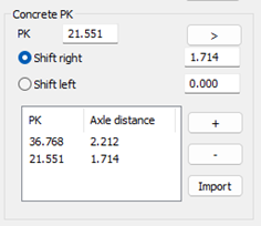
Specific Stations: In the section of the same name, we insert the stations and offsets with respect to the alignment on which we are going to insert the object.
Angles: The angle of insertion of the object is indicated, it can be made relative to the alignment (direct or reverse direction) or a specific angle in the plane.
Scale: The insertion scale of the block that has the object associated with it in the drawing.
Insertion of objects in plan
Inserting 3D Objects
|
|