3.8. CAD drawing
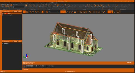
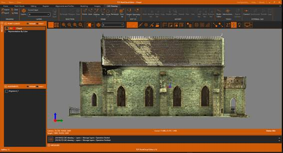
1. Hide the alignment and set Right View. Activate the CAD Drawing ribbon and on the ribbon and activate the Point and End Point references.
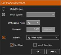
2. Now let's define a reference plane to draw safely on the façade. To do this, activate the Set Plane Reference icon. In the dialog, select the Define method with the By Three Points option and click OK.
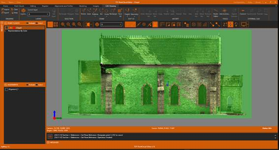
3. With the point reference activated, designate three points on the façade and the plan will be represented with a transparency.
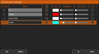
4. On the toolbar, click the layers control and click ADD to create a new Facade layer with Cyan color and linewidth 3. Also select it as active and press OK.
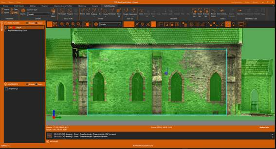
5. In the DRAW group, activate the Rectangle tool and draw it as in the following figure. Press button Keep for keeping the drawing visible.
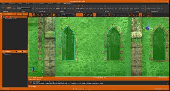
6. In the DRAW group, activate the Polyline > Polyline 2D tool and draw the outlines of the windows as in the following figure. Press the Shift key to draw an arc, Enter key to finish, Esc to cancel, Del to undo, and C to close.
7. On the toolbar, disable the Set Plane Reference icon and answer yes to the following question, accepting all proposed parameters.

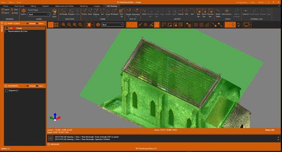
8. Create a new Roof layer with Magenta color and color 3 and set it as active.
9. Create a new reference plane by three points on the cover, disable the Keep Visible button and draw a rectangle as in the following figure.
10. Optionally, export the drawing made by clicking the Export icon in the DRAWING group.
11. It is also possible to import a drawing into the same coordinate system. To do this, activate layer 0 and hide the Roof and Facade layers. Within the DRAWING group, click the Import icon and choose the file Capilla1.dwg inside the 2-SCANNER folder. Test the effect of the Keep Visible button to control the visibility of the drawing.