6.2. Label Slopes and Elevation Differences |
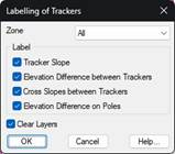
This option is very useful as it will allow you to create a slope and elevation difference plan from all the information about the trackers and the current surface. When you run this command, the following window will appear in which you can decide what type of information you want to label.
Zone: We select the zone on which to act. We also have the possibility of labeling in all zones of our project.
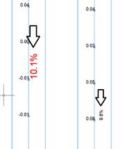
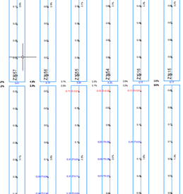
Tracker Slopes: The longitudinal slope of the trackers is labeled. In the event that the slope exceeds the maximum admissible slope (established in the zone properties), it will be labeled in another color and in a different layer.
Elevation Difference between Trackers: This option will label the difference in elevation between the ends on vertically aligned trackers. As in the previous point, it will be labelled in a different color and layer in the event that it exceeds the maximum permissible height difference. Also, to differentiate errors, the size of the texts, in the event that it exceeds the threshold, will be double the configured by default.
Transverse slope between Trackers: In this case, the existing slope between parallel trackers will be labeled. This slope will be calculated at the ends of each tracker. As in the previous options, in the event that the slope exceeds the maximum established in the corresponding area, it will be labeled with a different color and on a different layer.
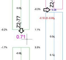
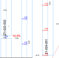
Elevation Difference in Poles: The difference in elevation between the current surface and the tracker grade is shown in the position of the poles. If the pole is within the Clearance constraints, the elevation difference will be labeled as correct.
In the event that the pole is outside the Clearance, the difference in elevation will be labeled in a different color and layer, in order to differentiate it from the previous ones. In addition, in this case, the excess with respect to the corresponding Clearance will be labeled in parentheses. A "C" will be added to the same text if it is being cut or a "F" if it is a fill.
In the image above we have a Positive clearance of 0.10 and negative one of 0.20.
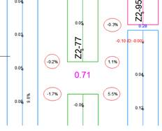
Finally, you can display a partial plan with the different labels drawn.