The structure of the slope to be defined is defined by vectors (similar to Definition of Ditch) by entering the dimensions of its respective vectors.
The program indefinitely extends the last vector until it intersects natural terrain.
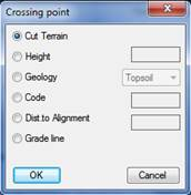
Once the slope to be applied is selected, the following window is displayed to indicate where to apply the slope in question.
Cut Terrain: The last slope vertex extends until it intersects with natural terrain.
Height: The slope will be extended up to a specific height. This value is applied vertically from the slope’s connection point.
Code: For this case the cross-section must be coded, so the slope will stretch to the cross-section vertex with the code specified on the side indicated. In such a case the slope definition is irrelevant as the slope is obtained from the cross-section vertex with the code specified.
Dist. to Alignment: In this last case a distance to the horizontal alignment is specified and the slope is created from the section connection point up to the point on the natural terrain whose distance to the horizontal alignment is that specified in this option. The same as the previous, it is independent of the defined slope as the slope is marked by the value of the distance to the horizontal alignment.
Grade line: In the latter case, a grade line is used as the reference for the extension of the slope, and on selecting this option the program will request the grade line file and will extend the slope in question to the height of the grade line in the corresponding station.
 Deletes the selected cutting slope assignment.
U.O.: Clicking on this option will enable us to assign a works unit to the slope assignment executed. The procedure for managing the works units is similar to that applicable to the Pavement Layers section. Works units can be assigned for each of the slope assignments executed.
We will then have the option of generating the corresponding reports in accordance with the assigned works units using the Measurements options.
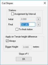
For the insertion or editing operation, as well as selecting the current slope, we must indicate the station at which said slope would be assigned and with this in mind, once the fill slope has been selected the following window will appear.
Assignments can be made to a specific station or between a given station interval. To do this, you simply deactivate or activate the “Interval Assignment” box. Stations can also be designated graphically.
In addition, in this window you can indicate if the slope will always be inserted or if its insertion will depend on the height difference of the application point of the ditch with respect to the natural terrain.