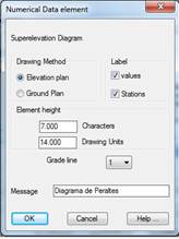
This numerical data element can only be represented if a segment has been selected. It calculates the superelevation diagram of the horizontal alignment associated to the segment and then draws it. The dialog box shown below is then displayed A description of its characteristics follows.
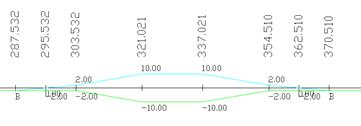
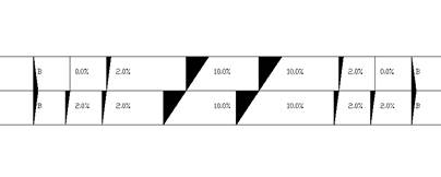
Drawing method: Represent the two ways MDT can use to draw the superelevations. An example of each of them follows.
Front View:
Top View:
Label: Indicates whether one wishes to label both the stations and the superelevation values. These controls are only valid should the superelevation be in the elevation drawing.
Element Height: Represents the distance to the immediately preceding numerical data element. This value can be expressed in two different ways:
· In number of characters
· In drawing units
When either of them is validated, the other value is automatically recalculated.
Message: Text that will appear as the element’s title on the numerical data drawing.