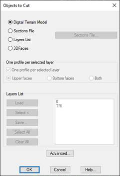
By activating this button, one selects the data source from which one wishes to obtain the profiles –in other words, from an MDT surface, a set of contour lines, a three-dimensional grid, a road section file, etc.
The dialog box that is displayed when this option is executed appears below. It is commented on further below.
There are different options for obtaining cross-sections, depending on the data source one wishes to use in order to generate them. The different methods are described below.
Digital Terrain Model: Uses the surface generated by MDT as a data source. It should have been previously selected in the main dialog box. This option is advisable when the model has been correctly obtained, since it includes height and orientation towards break line information, making it possible to obtain an accurate intersection with all the elements.
Sections File: In this case, the profiles are generated from a section file. When this option is selected, one has to select the section file with one will work. The sections definition and generation are detailed in the Contour Lines section.
Digital Elevation Model: In this case, the profiles are generated from a surface or Grid File. Their definition and how they are handled are described in the Maps section of this manual.
Layers List: This option allows one to cut any drawing element with elevation. In order to do so, the relevant layers whose elements are represented in 3D are selected using the cursor. The digital model can also be included in the selection by marking the TRI layer. Activating this option enables the Layers List box, from which the layers containing the 3D information can be selected.
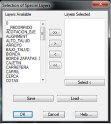
In this latter option, if the name of an element’s layer to be considered is unknown and its position in the drawing area is known, the Select button is simply clicked. At that moment, the program goes to drawing mode and the program requests objects to be selected. This operation should be executed for all of the elements selected.
The Save option is used when one wishes the set of layers to be saved in an ASCII file with the .CAP extension. The program superimposes a window called Save Layers List containing the project’s directory and proposes the current drawing as a name, which can either be validated or changed. When validated, one goes back to the previous window. Once this operation has ended, one can understand the utility of the Load button, seeing as in all subsequent operations involving longitudinal or cross-section cuts the layers can be selected by clicking this button and selecting the name of the relevant layers file.
When this option is selected, the Advanced button is enabled, so that information on the objects associated to the layers is included when profiles are obtained from the layers selected in the dialog box shown below. Object heights are interpolated.
By activating the corresponding option in configuration, one can decide whether or not polylines with a height of zero are to be cut.
3D faces: If we activate this option we have the possibility to obtain the profiles from the 3d faces of the selected layers.
· One profile per selected layer: If we select several layers and this option is activated, it will generate a cross-section for each of the selected layers. If the option is not enabled, it will create a single profile with all the information.
· Upper Faces: At the generation level, only consider faces that are oriented upwards.
· Bottom Faces: At the generation level, only consider the faces that are facing down.
· Both: Consider the above two options for profile generation.
Initial Station: The initial station assigned to the horizontal alignment’s initial position is entered in this box. The default value is either zero or the start of the horizontal alignment.
Final Station: The final station up to which one wishes to obtain the cross-sections is entered. Its default value will be the last station on the horizontal alignment selected.
Draw cross sections: If we enable this option, after successfully generating the cross sections the drawing thereof will be executed automatically.
Profile Length: The cross-sections’ length is entered in this control by indicating the meters to the left and the right of the horizontal alignment.
Should the horizontal alignment or polyline from which one wishes to obtain the profile go beyond the area included in the digital model, its ends are interpolated from the last two vertices found before the first and last intersection in the model.
Cut Lines: This option allows one to set a series of polylines that will serve as a reference to calculate the ends of the cross-sections. The program will extend the cross-section until it finds an intersection with any of the polylines entered. The maximum extension length is as set in the Profile Length field.