A list containing the X, Y and Z coordinates of the cross-section’s characteristic points is displayed with this option. Optionally, one can obtain a setting out list from the stations of these points.
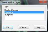
When this command is executed, a segment is requested, which must contain information on the horizontal alignment, natural terrain, grade line and cross-section template (see Definition of Segment). Next, in the case that roadbed is assigned, a window is displayed to select the layer of roadbed for setting out:
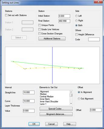
Once the layer of roadbed is selected, a message appears with the possible errors found in the segment and then after accepting this, the following window appears for establishing the setting out lines.
Stations: The possibility of indicating the setting out stations exists, where Station 1 is the base station and Station 2 is the reference station. They can either be selected or their names entered in the respective boxes.
Initial station: Initial station from which the setting out will be performed.
Final station: Final station up to which the setting out will be performed.
Unique Points: If the check box is enabled, the horizontal alignment’s unique points will be added to the list.
Grade Line Vertices: If the check box is enabled, the segment’s grade line vertices will be added to the list.
Template Changes: If the check box is enabled, all the stations where any Alignment Template Assignment changes have been made will be added.
Additional Stations: The possibility exists of indicating the command to calculate some additional stations.
Side: Indicates the side of the cross-section to be set out: Left, Right or Both.
Others: If this program option is activated, a list showing slope crown and feet height differences with regard to the vertex whose code coincides with the value entered in the Code box will be displayed.
If no value is entered in the Code field, the program displays the height difference with regard to the previous or next vertex, depending on whether the cursor is to the right or the left of the horizontal alignment.
Interval: Value indicating the interval with which the setting out is to be performed. The possibility of indicating a different interval for Curves also exists.
Elements to Set Out: List of the characteristic cross-section points which can be set out. If any of them are selected graphically, it will appear marked on the image above. This image is a preview of the initial station of the cross-section selected. It is possible to make a multiple selection.
Layer Thickness: this value will be taken away from the height resulting from the setting out. As such, in the event it is positive the result of the height will be lower and in the event, it is negative the result of the height will be greater.
Roadbed Thickness: this value is subtracted from the setting out result. If it is positive the elevation result will be lower and if it is negative the elevation result will be higher.
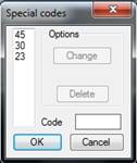
Special Codes
In addition to the elements to be set out, one can enter one or more specific codes on which one wishes to obtain information. The dialog box used to manage this type of codes is shown below.