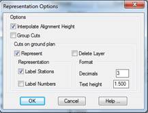
These options allow one to configure how the cross-sections that will be obtained are to be represented.
Interpolate Alignment Height: If this option is activated, the program will automatically generate a height on the horizontal alignment of each cross-section. If the source of the data is not an MDT surface, this height will be interpolated between the adjacent vertices.
Group Cuts: This allows one to group all the cross-sections drawn in a single block so that they can be more easily deleted or handled with CAD.
Represent: When this option is activated and the cross-sections are obtained, it will draw the profiles obtained on the ground plan.
Some options to configure the representation of ground plan cuts are additionally available:
Label Stations: One indicates whether ones wishes to label the stations corresponding to each cut.
Label Numbers: One indicates whether one wishes to show the number corresponding to each of the profiles generated.
Decimals: Number of decimals to use to label the stations.