This command is very useful for quickly obtaining an idea of the terrain. This command allows one to indicate the profile desired and represents it in a window. This representation can be scaled in order to view the slope changes clearly through the use of the Vertical Factor box. Additionally, information on the distance and height of each of the vertices is labelled when the mouse’s cursor is situated over them. When the dialog box is validated, the process is automatically repeated until it is cancelled.
The profile to be calculated can be composed of as many sections as we want. When we do not wish to add any more sections, right click with the mouse and the profile view will appear automatically.
The profile to be generated will be marked with a polyline which will be automatically deleted once it is displayed on the screen.
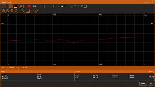
The window will contain the following information on each cut calculated:
· Slope: Minimum, average and maximum.
· Height: The initial and final height and the minimum and maximum height.
· Length of the profile.
Draw: this option will enable us to draw the instantaneous profile created as if it were a longitudinal profile. The “Draw Simple Profile” command will be executed directly.
Instantaneous profiles can only be created when the surface has been defined, otherwise the program will display the warning message “ERROR: There are no defined surfaces”. If no intersection is found with the lines comprising the digital model, the warning message “There are no intersections with the surface” will appear on the screen.
In the event the profile to be drawn features an area in which there is no information on the surface (islands, for example), it will be represented in the drawing with a blue trace.
The ends of the alignment specified by the user are obtained from the digital model.
The image below provides an example of a quick profile and describes each of the different controls:
It will enable us to record the quick profile as a longitudinal profile. File with a LON extension.
We activate / deactivate the graphic grid.
We define the background color in the viewer.
We manage the layers of the drawing. The option of customizing the name and color of the layers.
The option of increasing or reducing the thickness of the line representing the profile of the section.
Model scale.
Zoom in.
Zoom out.
Zoom in on a particular window.
Zoom in on all visible elements.
Enables us to measure the distance between two points.
This button will show us the distance between two selected points on the X and Y alignment.
Removes all existing measurements in the drawing.
This option will allow us to remove or delete the selected measurements.
These buttons are used to select the type of clamp when selecting the point on the screen. They are used for the aforementioned measurement options.