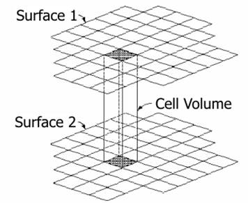
This command calculates the cutting and fill volumes from two grid files obtained using the Maps > Create Grid from Surface and Maps > Create Grid from Contour Lines commands. Both files should be generated with the same cell size. The smaller this value is, more precise is the calculation. However, grid files are larger and processing is therefore slower.
The calculation process is as follows: The average height is measured for every two cells whose 2D coordinates coincide from their four vertices. Then the heights are compared. If the difference is above the tolerance set, the volume between both cells is calculated and the cutting or fill volume is added in accordance with its sign. The formula used to calculate the volume is as follows:
where:
Vi = Volume of cell i
D = Size of the cell
Z1 = Average height of the cell in surface 1
Z2 = Average height of the cell in surface 2
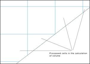
If the partial cells on the boundary” option is activated in “Settings > Volumes”, in the event the cells on the calculation perimeter are only partially affected by the calculation of volume, only the affected region of the cell in question will be processed.
.
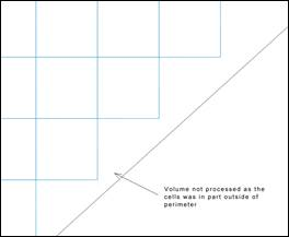
If the option is not activated, the cell which is partially beyond the boundary will not be processed.
|
Use partial cells on the boundary
|
|
|
|
|
ACTIVATED
|
DEACTIVATED
|
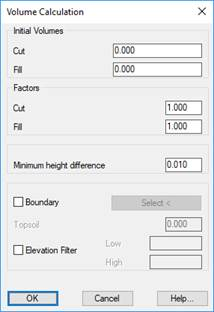
When executing this command, first of all, the program shows a dialogue box where you can enter some Initial Volumes for cut and fill, which the program adds to the final calculation result. You can also introduce factors that multiply the volumes obtained.
Minimum height difference. The minimum difference in meters at which the volume is calculated.
Boundary: We can select a polyline which delimits the surface we wish to analyze.
Vegetal Soil: If a Vegetal Soil Thickness is introduced, the program internally lowers the height of the first mesh indicated meters, before proceeding with the calculation. This option will only be enabled in the case of selecting a boundary action, a boundary in which the displacement of elevation will be made for the calculation.
Elevation Filter: By enabling this box we will be able to set the minimum elevation and maximum elevation values between which it is wished to make the calculation.
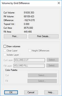
Once the two grid files to be used have been selected, the program calculates the volume by superimposing the two grids and provides information on the results obtained.
The Print button creates a list where the names of the grid files and the results obtained are displayed. Additionally, the Print Details button adds a detailed breakdown of each of the cells to the above-mentioned list.
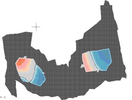
One can obtain a graphic representation of the results by activating the Draw Volumes check box. This consists of a grid that is only defined in the area defined by both grid files. Each cell will have a color indicating if the area is in a cutting, fill or whether it does not contribute to volume within tolerance set in the configuration. There is the possibility of assigning at the drawing a range of colors both for the cut and fill; with this in mind, we have the option of selecting the corresponding color palette.
In addition, if one activates the Height Differences check box, a text containing the height differences between the both grids will be drawn within each cutting or fill cell.