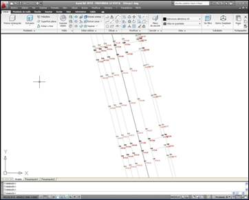
For some linear works, power lines, road alignments, etc. for which one does not have a surface of the area available but isolated surveying points near the horizontal alignment, the option enables one to obtain it without the need to triangulate. A longitudinal profile is thus obtained, whose heights are directly assigned from the points close to the horizontal alignment and within the margin set in the command.
Any points that are found at a level that cannot be triangulated will not be considered. For further details, consult the Points section in the Customization Manual.
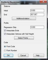
When the command is executed, MDT initially request the horizontal alignment from which the profile will be generated. The following dialog box is then displayed, which is described below.
Initial station: Allows the longitudinal profile’s initial point to be specified.
Final station: The station up to which the longitudinal profile will be obtained is likewise specified.
Additional stations: Used to select any additional stations that we wish to include in generating the longitudinal profile. The heights of these stations will be interpolated between the previous and following points with known heights.
Regression Strip: Sets the interval to the left and the right of the horizontal alignment where the points projected onto the alignment will be found.
Interpolate Ends: Indicates whether the ends of the longitudinal profile are to be interpolated should no points be found at the ends. If they are found, the program will interpolate in a linear fashion with regard to the two distances before and after the initial and final point respectively.
Interpolate Vertices with Null Height: This option is useful when there are points that project onto the horizontal alignment with null or zero height. If this option is activated, the program will automatically interpolate these points. In the case that vertices with null height exist and this option is not activated, the vertices in question will be eliminated from the profile generated.
Select Points: Allows one to select the points that will take part in the profile’s generation. Point selection may be performed in many ways: by numbers, codes, etc. For further details, consult the section on Points.
Codes: Sets the representation of codes on the longitudinal profile. It may be configured in two ways:
· Point Code The code of the projected point appears in the code of the longitudinal profile’s vertex.
· Point Number: The number of the projected point appears in the code of the longitudinal profile’s vertex.
Finally, a file with .LON extension is generated. Its codes will include the point which has been used as a reference to generate the longitudinal profile. An example of a longitudinal file obtained by regression is shown below.
|
0.000
|
98.530
|
74
|
|
6.840
|
98.560
|
75
|
|
20.427
|
98.620
|
76
|
|
33.399
|
98.620
|
77
|
|
46.306
|
98.650
|
78
|
|
60.333
|
98.610
|
79
|
|
65.539
|
98.570
|
80
|
|
78.661
|
98.500
|
81
|
|
83.795
|
98.490
|
82
|
|
94.576
|
98.510
|
83
|
|
112.160
|
98.530
|
84
|
|
127.585
|
98.530
|
85
|
|
137.197
|
98.540
|
86
|
|
152.073
|
98.530
|
88
|
|
163.356
|
98.520
|
89
|
|
171.644
|
98.520
|
90
|
|
180.727
|
98.510
|
91
|
|
191.929
|
98.520
|
92
|
|
198.614
|
98.510
|
93
|
|
204.439
|
98.510
|
94
|