This command allows one to convert a flat cartography containing 2D entities into 3D cartography, in order to prepare it to obtain profiles or a surface. The objects processed by this command include lines, polylines and arcs. The program displays the following toolbar from which one can select the different methods available, which are described below.
The icons from left to right are described below:
Zero Height: One simply has to select the objects to be assigned a height of zero.
Constant Height: The program first requests the height. Then one has to select the objects to be elevated.
Ends: Once an object has been selected, the program requests the initial and final heights. The program takes the end closest to the point selected as the start of the object. Should the object be a polyline, the height is interpolated at intermediate vertices. Should the object be an arch, it is discretized and converted into a polyline before the heights are assigned.
Variable: This option allows one to assign different heights to an object’s vertices. If the object selected is a line or an arch, this option behaves like the Ends command and requests the initial and final heights. Should a polyline be selected, the program situates itself at the first vertex and displays the following sub-menu in the command line:
Height/Reference/Back/Move/Exit <Interpolated>:
If a Height is entered, it is assigned to the corresponding vertex. If Reference is chosen, the program will request one to select a point. It will then take the same height as the point selected. The Back option allows one to go back in order to edit the last vertex. If Move is chosen, the vertex’s X and Y coordinates can be moved. Exit takes one back to the tool’s main menu. If <Enter> is keyed in directly, height will be interpolated from the other vertices’ heights.
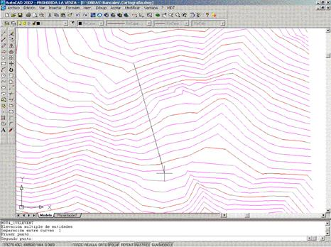
Multiple: This option allows one to raise several contour lines at the same time. The program initially requests the separation in height between successive contours and its sign. Then two points are entered, so that the line between them intersects several contour lines. Finally, the initial height is entered. With these data, the program assigns the first height to the first curve. It then successively increases the height using the separation entered and assigns it to the next contour line.
Surface: Once a set of objects has been selected, the program assigns each of their vertices the height corresponding to them in the current surface. It also requests one to specify if one wishes to process the polylines that are already in 3D or just the 2D polylines. Should the surface not be defined, the program attempts to assign heights to each vertex on the basis of the drawing’s points.
Inclined: One can assign heights of an inclined plane to a polyline’s vertices using this option. Once the polyline has been selected, the program requests a point, its height, the direction of the slope on the plan, and for the slope (in percentage terms).
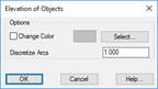
Options: A dialog box is displayed allowing one to specify the parameters affecting all the above-mentioned modes. If the Change Color option is activated, the color each object modified by this command will change color and assigned the one appearing on the right-hand side of the box. This is useful to modify large drawings, so that already processed objects can be differentiated. Additionally, the Arch Discretization box indicates the discretization value of arcs and polyline arch segments that are elevated.
Tool Bar: Displays this command’s tool bar on the CAD user interface, allowing it to be subsequently used.