This command allows one to represent the cutting or fill slopes in the drawing.
The program initially requests the polyline from which the lines marking the slopes will start. Then the mode in which the tool will be executed in the command line is selected:
Partial: A polyline of origin is selected.
Total: The polylines of origin and reference are designated.
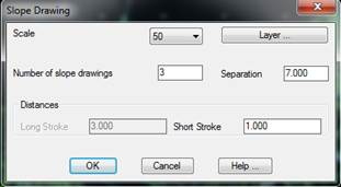
Once the polyline(s) are selected, MDT will display the following dialog box, where the way polylines are drawn is configured.
Scale: Sets the scale of the slope drawings.
Layer: The layer in which one wants to draw the slope drawings is selected.
Number of Slope Drawings: Number of short slopes to be represented between two long slopes.
Separation: Separation interval between two long marks.
Long Mark Distances: Length of long mark. This value is only valid should the Partial method be chosen, as the Total method uses the second polyline as a reference for the long mark’s length.
Short Mark Distances: Length of the short marks to be drawn.
Once the dialog box is validated, MDT proceeds to draw them.