When this command is executed, either the natural terrain cross-sections (.TRA extension), skew profiles (extension .TRE) or the segment containing all the information on the road generated (see Definition of Segment in the Alignments section) is drawn.
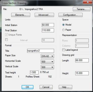
When this command is executed, the program initially displays the .TRA and .SEG file templates and goes to the last folder used. By selecting or keying in a name, one goes to the parameter definition window, where the different options applied to drawing cross-sections can be configured.
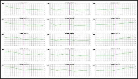
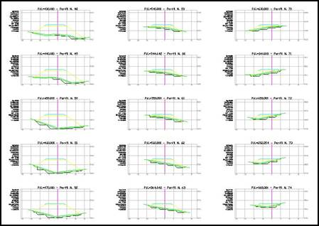
Once all the window’s parameters have been set, the source of the top left corner where one wishes to commence their representation is requested. The profile matrixes are then drawn from left to right and top down depending on the drawing direction set.
For continuous format drawings, the project’s title and reference are displayed on top left-hand corner. If any of the formats available is selected, the profiles will be distributed on the sheet selected, and as many sheets as may be necessary will be inserted. Each of the sheets contains a series of attributes detailing the drawing’s characteristics: horizontal and vertical scales, title, reference, sheet number, total number of sheets and date. To change or create new sheets or attributes, see the Customization Manual.
The following image shows an example of cross-sections drawn:
And this image shows an example of a segment drawn:
The controls in this dialog box are described below.
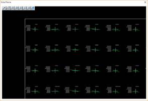
Preview
Prior to drawing the profiles pressing this tab gives us the option of viewing the distribution of the profiles. For example, this option is interesting when drawing on sheets as it enables us to view the distribution of the same and to change the Height and Length parameters with the aim of removing one of the sheets.