Creating a surface is equivalent to generating the digital terrain model. That is why this command performs the triangulation process in order to obtain the triangular irregular network. Each of the changes made to the original digital model can be saved as a different surface.
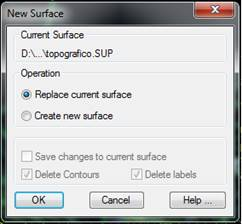
First, if a surface is associated with the drawing, a window is displayed for selecting whether to replace the current surface or create a new one. In the latter case, activate the option Save changes to current surface.
If the program recognizes that a contour is drawn, it enables the option Delete Contours. When it is activated, it deletes the polylines of the layers configured as contour layers at the end of the triangulation process.
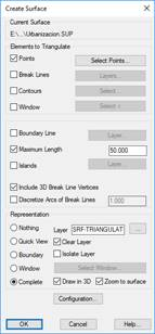
If no current surface exists, or the option Create new surface was selected in the previous window, the program will request a file location for saving the surface. Next, the Create Surface window is displayed:
The Elements to Triangulate options box allows one to specify the different elements to be used to create the surface. One can triangulate Points, Break lines and Contours at the same time. Depending on whether each of the options is enabled or disabled, the relevant button on the right is enabled to allow one to specify the drawing elements that will be used.
Points: This option should be activated if one wishes to triangulate surveying points. The program triangulates all the points on the drawing by default, except those whose level cannot be triangulated. One can specify a different set of points by clicking on Select Points in the Point Selection window.
Break Lines: This option allows one to decide on the use of break lines. By clicking the Layers button, one can select the layers where the break lines are drawn through the Layer Selection window.
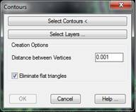
Contours: Should the drawing contain contour lines; one can use the polylines to create vertices on the surface. These polylines behave like break lines. The following window appears when the Select button is clicked.
The Select Contours button allows one to graphically select the contour lines one wishes to use to perform the triangulation. The option also exists of using the Select layers button to specify the contour lines to be triangulated by selecting the layers containing them.
Due to the fact that sometimes the polylines defining a contour line may have too many vertices, the program can filter them to discard vertices that are very close together. By doing this one can manage to reduce the number of vertices included in the surface and therefore processing time. The Distance between Vertices parameter controls the distance below which vertices are ignored. The Eliminate Flat Triangles box decides whether or not to use a subsequent process that avoids forming flat areas where contour lines are very tight, on crests, steep depressions, etc.
Once a decision has been made on which elements to triangulate, one can specify if the contours surrounding the scatter plot is to be used, or if Islands will be considered in the triangulation. Simply activating the corresponding options and specifying the layer where the polylines representing these objects is enough for both cases. If a boundary is not specified, it is important to specify the Maximum Length of the external triangles’ sides, so that one can prevent areas being formed whose vertices are very distant.
In addition, the Include 3D break line vertices option is possible. This option considers the coordinates of the vertices belonging to the 3D polylines in the layers selected as if they were triangulation vertices. If the break lines contain arcs, the parameter Discretize Arcs of Break Lines allows for specifying the separation between the vertices that the program will add to the surface along them.
Lastly, the way in which the surface is represented is controlled at the bottom of the dialog box. There are different possibilities, which are the same as for the Draw Surface command.