This command will allow us to convert to cross sections a series of lines on the ground plan drawn in the mapping. With this in mind, we will initially designate the working alignment and then the cross sections file in which the read drawing profiles will be stored.
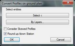
Once the alignment and the file have been selected, the following window will appear in which we will establish all the settings required for profile generation.
Select elements: We will be able to select the lines or polylines that represent the profiles on the ground plan either graphically or by indicating the layer or layers on which they are situated.
Consider Skewed Profiles: In the event that the lines drawn on the ground plan which represent the cross sections are not normal for the alignment, if this option is enabled these profiles will be generated, otherwise they won't.
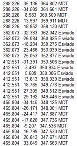
If the cross sections are generated, they will be associated with the code “Skewed” to distinguish it from the other profiles. A cross sections will be regarded as skewed when the angular difference from the axis norm is greater than one degree.
Round up/down Station: If we enable this box, the stations associated with the drawing cross sections read will be rounded up/down in multiples of 0.5.
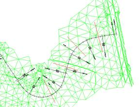
An example has been shown below of an application in which the drawing profiles have been read (red lines), having enabled by default the option “Consider Skewed Profiles” and disabled the “Round up/down stations” option.