This numerical data element is used to insert drawing blocks along the profile. In order to do so, the insertion of blocks should have been configured in the main longitudinal drawing window. For further details on configuring the representation of these, see the Alignment > Block Definition command.
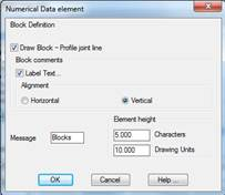
Depending on how the blocks are configured, they are either inserted as another numerical data element (Numerical Data mode) or on the profile drawn (Terrain mode). The dialog box shown below is then displayed A description of its characteristics follows.
Draw Block – Profile joint line: This option only makes sense in the case of drawing blocks over the terrain and will draw a line from the insertion point to the profile projection point.
Label Text: If we check this option, as well as drawing the block it will label the comment associated with the code corresponding to the code data base.
Alignment: Offers the choice of vertical or horizontal when labelling text.
Element Height: Represents the distance to the immediately preceding numerical data element, expressed in number of characters. This value may be expressed in two different ways:
· In number of characters
· In drawing units
When either of them is validated, the other value is automatically recalculated.
Message: Text that will appear as the element’s title on the numerical data drawing.