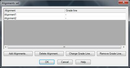
This utility generates a list containing the coordinates, stations and height differences of the intersections of a set of coordinates or segments. If the drawing is associated to a project, the program deduces which set of horizontal alignment to check. Otherwise, the program requests a set of alignment and/or segment files. The following dialog box is then displayed:
The Add Alignments button allows one to include more files to the current horizontal alignment set. If a horizontal alignment file is included, the program cannot know which is the grade line file. It is therefore not recommended. If a segment file is included, the program includes the alignment and the grade line belonging to it.
An alignment (and its associated grade line) can be removed from the set by the Delete Alignment button, so that it is not used in the calculation. Delete Grade Line works in a similar way. It leaves the alignment but deletes the grade line. In both cases, the files are not deleted. The command simply stops using them.
Should one wish to modify a grade line associated to a horizontal alignment, a horizontal can be selected from the list, Change Grade Line clicked, and the appropriate file selected.
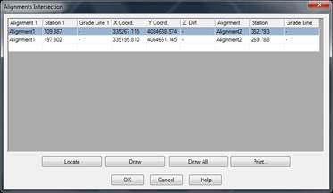
Once the set of alignments to be considered is modified, the intersections dialog box is displayed.
Locate centers the CAD work window at the intersection selected from the list.
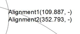
Draw creates an annotation on the intersection selected from the list on the drawing. The names of both horizontal alignments are shown, as are the intersection’s stations and heights between parenthesis.
Draw All draws the annotations corresponding to all the intersections calculated.
Print launches the list’s printing.
When a horizontal alignment is associated to a grade line, the cell containing grade line height can be modified. When it is changed, the program modifies the relevant grade line.